
Data Sheet


©2006 Fairchild Semiconductor Corporation www.fairchildsemi.com
FODM30XX Rev. 1.2 7
FODM30XX — 4-Pin Full Pitch Mini-Flat Package Zero-Cross Triac Driver Output Optocouplers
Typical Application Information
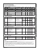
Figure . Static dv/dt Test Circuit
800V (FODM3082)
Vdc
(FODM3083)
600V (FODM3062)
(FODM3063)
R = 10 kΩ
C
TEST
X100
SCOPE
PROBE
PULSE
INPUT
MERCURY
WETTED
RELAY
78V (FODM3062, FODM3063)
504V (FODM3082, FODM3083)
0 VOLTS
APPLIED VOLTAGE
WAVEFORM
dv/dt =
0.63 V
max
R
TEST
D.D.UU..TT..
τ
RC
V
max
== 800V (FODM3082, FODM3083)
=600V (FODM3062, FODM3063)
=
378
τ
RC
(FODM3062, FODM3063)
=
504
τ
RC
(FODM3082, FODM3083)
τ
RC
Note:
This optoisolator should not be used to drive a load directly. It is intended to be a trigger device only.
1. The mercury wetted relay provides a high speed repeated
pulse to the D.U.T.
2. 100x scope probes are used, to allow high speeds and
voltages.
3. The worst-case condition for static dv/dt is established by
triggering the D.U.T. with a normal LED input current, then
removing the current. The variable RTEST allows the dv/dt
to be gradually increased until the D.U.T. continues to trigger
in response to the applied voltage pulse, even after the LED
current has been removed. The dv/dt is then decreased until
the D.U.T. stops triggering. tRC is measured at this point
and recorded.
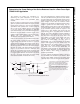
Figure . Inverse-Parallel SCR Driver Circuit (240 VAC)
V
CC
R
in
1
2
4
3
240 VAC
SCR
360 Ω
R1 D1
SCR
R2 D2
LOAD
Suggested method of firing two, back-to-back
SCR’s, with a Fairchild triac driver. Diodes can
be 1N4001; resistors, R1 and R2, are optional
330 ohms.
Note:
This optoisolator should not be used to drive a load directly. It is intended to be a trigger device only.
FODM3062
FODM3063
FODM3082
FODM3083