
Data Sheet


FNC42060F / FNC42060F2 Motion SPM® 45 Series
©2013 Fairchild Semiconductor Corporation 10 www.fairchildsemi.com
FNC42060F / FNC42060F2 Rev. C3
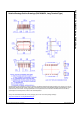
Mechanical Characteristics and Ratings
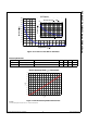
Figure 9. Flatness Measurement Position
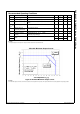
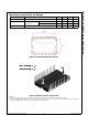
Figure 10. Mounting Screws Torque Order
2nd Notes:
9. Do not make over torque when mounting screws. Much mounting torque may cause ceramic cracks, as well as bolts and Al heat-sink destruction.
10. Avoid one side tightening stress. Figure 10 shows the recommended torque order for mounting screws. Uneven mounting can cause the ceramic substrate of the SPM
®
45
package to be damaged. The pre-screwing torque is set to 20 ~ 30% of maximum torque rating.
Parameter Conditions Min. Typ. Max. Unit
Device Flatness See Figure 9 0 - + 120 m
Mounting Torque Mounting Screw: M3
See Figure 10
Recommended 0.7 N • m 0.6 0.7 0.8 N • m
Recommended 7.1 kg • cm 6.2 7.1 8.1 kg • cm
Weight - 11.00 - g
1
2
Pre - Screwing : 1→2
Final Screwing : 2→1
1
2
Pre - Screwing : 1→2
Final Screwing : 2→1