
Data Sheet


© 2012 Fairchild Semiconductor Corporation www.fairchildsemi.com
FLS0116 • Rev. 1.0.2 6
FLS0116 — MOSFET Integrated Smart LED Lamp Driver IC with PFC Function
Functional Description
The FLS0116 is a basic PWM controller for buck
converter topology in Continuous Conduction Mode
(CCM) with an intelligent PFC function that uses a
digital control algorithm. An internal self-biasing circuit
uses the high-voltage switching device. The IC does not
need an auxiliary powering path to the VCC pin typical
in flyback control ICs or PSR product family.
When the input voltage applied to the HV pin is within
operating range (25 V to 500 V), the FLS0116
maintains a 15.5 V DC voltage at the VCC pin for stable
operation. The UVLO block functions such that when
the V
CC
voltage rises higher than V
CCST+
, the internal
UVLO block releases and starts operation. Otherwise,
the V
CC
goes down to the V
CCST-
and IC operation stops.
Normally, the hysteresis function provides stable
operation even if the input voltage is operating under
very noisy or unstable circumstances.
The FLS0116 has a “smart” internal digital block for
determining input condition: AC or DC. When an AC
source with 50 Hz or 60 Hz is applied to the IC, the IC
automatically changes its internal reference signal,
which is similar to input signal, for creating high power
factor. When a DC source connects to the IC, the
internal reference immediately changes to DC.
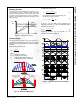
Soft-Start Function
The FLS0116 has an internal soft-start function to
reduce inrush current at startup. When the IC starts
operation following an internal sequence, the internal
reference slowly increases for a pre-determined fixed
time. After this transient period, the internal reference
goes to a steady-state level. In this time, the IC
continually tries to find phase information from the VCC
pin. If the IC succeeds in getting phase information, it
automatically follows a similar shape reference made
during the transient times, 7 periods. If not, the IC has a
DC reference level.
I
LED
T/2 = 1/(Input Frequency * 2)
7*(T/2)
Normal Operation
V
bridge
Figure 4. Soft-Start Function in AC Input Mode
Internal PFC Function: How to Achieve
High Power Factor
The FLS0116 has a simple, “smart”, internal PFC
function that does not require additional pins for
detecting input phase information or an electrolytic
capacitor for supply voltage stabilization. For achieving
high PF, the FLS0116 does not use the rectification
capacitor after the bridge diode. This is important
because the IC instead uses fluctuation in the signal on
the VCC pin. Basically, the VCC pin, which is supplies
power for the IC, has voltage ripple as well as the
rectification voltage after bridge, changing voltage level
according to the V
CC
capacitor value. Using this kind of
voltage fluctuation on the VCC pin, the IC can detect
the time reference and create the internal ZCD signal.
For precise and reliable internal reference for input
voltage signal, the FLS0116 uses a digital technique
(sigma/delta modulation) and creates a new internal
signal (DAC_OUT) that has the same phase as the
input voltage, as shown in Figure 5. This signal enters
the final comparator and is compared with current
information from the sensing resistor.
DAC_OUT
JFET Output
Voltage
Bridge Diode
Output Voltage
Input Voltage
Peak
ZCD
t
t
t
VCC
V
DD
Charging Voltage
JFET Output Voltage
t
V
bridge
Figure 5. Internal PFC Function
Self-Biasing Function
The self-biasing function, using an HV device, can
supply enough operating current to the IC and
guarantee similar startup time across the whole input
voltage range (80 V~308 V
AC
). However, self-biasing
has a weakness in high-voltage condition. Normally,
the HV device acts as constant current source, so the
internal HV device has power loss when high input
voltage connects to the HV pin. This power loss is
proportional to input voltage. To reduce this power
loss, one of the possible solutions is an additional
resistor between the input voltage source and the HV
pin, as shown in Figure 6.
D1
Fuse
C1 C2
L2
R2
FLS0116
CS
VCC
GND
RT
DRAIN
HV
ADIM
L1
L3
C3
R1
C4
BD
LED
R3
Figure 6. High-Voltage Application