
Data Sheet


© 2012 Fairchild Semiconductor Corporation www.fairchildsemi.com
FLS0116 • Rev. 1.0.2 2
FLS0116 — MOSFET Integrated Smart LED Lamp Driver IC with PFC Function
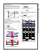
Block Diagram
GND
RT
VCC
HV
Reference
ADIM
JFET
AOCP
I
AD
UVLO
Q
R
S
TSD
Leading-Edge
Blanking
ZCD
DAC
Soft-Start
Digital Block
CS
Oscillator
-
+
LEB
-
+
time
VCC
ZCD
2.5V
FLS0116
DRAIN
7
8
1
3
4
5
2
Figure 2. Block Diagram
Pin Configuration
CS
VCC
GND
RT
DRAIN
HV
ADIM
FLS0116
Figure 3. Pin Configuration
Pin Definitions
Pin #
Name
Description
1
CS
Current Sense. Limits output current, depending on the sensing resistor voltage. The CS pin is
also used to set the LED current regulation.
2
VCC
VCC. Supply pin for stable IC operation; ZCD signal detection used for accurate PFC function.
3
GND
GROUND. Ground for the IC
4
RT
RT. Programmable operating frequency using an external resistor; the IC has pre-fixed
frequency when this pin is open or floating.
5
ADIM
Analog Dimming. Connect to the internal current source. Use to change the output current
using an external resistor. If ADIM is not used, connect a 0.1 µF bypass capacitor between the
ADIM and GND.
7
HV
High Voltage. Connect to the high-voltage line and supply current to the IC.
8
DRAIN
DRAIN. The drain pin of internal MOSFET