
Data Sheet

www.onsemi.com
5
FAN7930C — Critical Conduction Mode PFC Controller
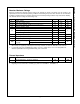
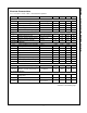
Electrical Characteristics
V
CC
= 14 V and T
A
= -40°C~+125°C, unless otherw ise specified.
Symbol
Parameter
Conditions
Min.
Typ.
Max.
Unit
V
CC
Section
V
START
Start Threshold Voltage
V
CC
Increasing
11
12
13
V
V
STOP
Stop Threshold Voltage
V
CC
Decreasing
7.5
8.5
9.5
V
HY
UVLO
UVLO Hysteresis
3.0
3.5
4.0
V
V
Z
Zener Voltage
I
CC
=20 mA
20
22
24
V
V
OP
Recommended Operating Range
13
20
V
Supply Current Section
I
START
Startup Supply Current
V
CC
=V
START
-0.2 V
120
190
µA
I
OP
Operating Supply Current
Output Not Sw itching
1.5
3.0
mA
I
DOP
Dynamic Operating Supply Current
50 kHz, C
I
=1 nF
2.5
4.0
mA
I
OPDIS
Operating Current at Disable
V
INV
=0 V
90
160
230
µA
Error Amplifier Section
V
REF1
Voltage Feedback Input Threshold1
T
A
=25°C
2.465
2.500
2.535
V
V
REF1
Line Regulation
V
CC
=14 V~20 V
0.1
10.0
mV
V
REF2
Temperature Stability of V
REF1
(
4
)
20
mV
I
EA,BS
Input Bias Current
V
INV
=1 V~4 V
-0.5
0.5
µA
I
EAS,SR
Output Source Current
V
INV
=V
REF
-0.1 V
-12
µA
I
EAS,SK
Output Sink Current
V
INV
=V
REF
+0.1 V
12
µA
V
EAH
Output Upper Clamp Voltage
V
INV
=1 V, V
CS
=0 V
6.0
6.5
7.0
V
V
EAZ
Zero-Duty Cycle Output Voltage
0.9
1.0
1.1
V
g
m
Transconductance
(
4
)
90
115
140
µmho
Maximum On-Time Section
t
ON,MAX1
Maximum On-Time Programming 1
T
A
=25°C, V
ZCD
=1 V
35.5
41.5
47.5
µs
t
ON,MAX2
Maximum On-Time Programming 2
T
A
=25°C,
I
ZCD
=0.469 mA
11.2
13.0
14.8
µs
Current-Sense Section
V
CS
Current-Sense Input Threshold
Voltage Limit
0.7
0.8
0.9
V
I
CS,BS
Input Bias Current
V
CS
=0 V~1 V
-1.0
-0.1
1.0
µA
t
CS,D
Current-Sense Delay to Output
(4)
dV/dt=1 V/100 ns,
from 0 V to 5 V
350
500
ns
Continued on the following page…