
Data Sheet

www.onsemi.com
16
FAN7930C — Critical Conduction Mode PFC Controller
R
ZCD
V
AUX
ZCD
Zero-Current
Detect
5
Vcc
N
1
V
REF
I
MOT
reset
Sawtooth Generator
C
MOT
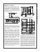
THD Optimizer
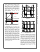
Figure 40. Circuit of THD Optimizer
V
ZCD
t
ON
t
V
ZCD
at FET on
t
ON
get shorter
t
ON
not shorter
t
ON
is typically constant over 1 AC line frequency,
but t
ON
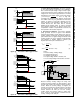
is changed by ZCD voltage.
Figure 41. Effect of THD Optimizer
By THD optimizer, turn-on time over one A C line period
is proportionally changed, depending on input voltage.
Near zero cross, lengthened turn-on time improves THD
performance.
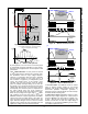
10. V
IN
-Absent Detection: To save pow er loss caused
by input voltage sensing resistors and to optimize THD,
the FAN7930C omits AC input voltage detection.
Therefore, no information about AC input is available
from the internal controller. In many cases, the V
CC
of
PFC controller is supplied by an independent pow er
source, like standby pow er. In this scheme, some
mis match may exist. For example, w hen the electric
pow er is suddenly interrupted during tw o or three AC
line periods; V
CC
is still live during that time, but output
voltage drops because there is no input pow er source.
Consequently, the control loop tries to compensate for
the output voltage drop and V
COMP
reaches its
maximum. This lasts until AC input voltage is live again.
When AC input voltage is live again, high V
COMP
allows
high sw itching current and more stress is put on the
MOSFET and diode. To protect against this, FA N7930C
checks if the input AC voltage exists. If input does not
exist, soft-start is reset and w aits until AC input is live
again. Soft-start manages the turn-on time for smooth
operation w hen it detects AC input is applied again and
applies less voltage and current stress on startup.
V
IN
t
V
OUT
V
AUX
MOSFET gate
I
DS
f
MIN
D
MAX
High drain
current!
V
COMP
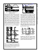
Though V
IN
is
eliminated, operation of
controller is normal due
to the large bypass
capacitor.
Figure 42. Without V
IN
-Absent Circuit
V
IN
t
V
OUT
V
AUX
MOSFET gate
I
DS
f
MIN
D
MAX
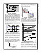
V
IN
Absence Detected
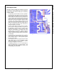
NewV
COMP
Though V
IN
is
eliminated, operation of
controller is normal due
to the large bypass
capacitor.
f
MIN
D
MIN
Smooth
Soft-Start
Figure 43. With V
IN
-Absent Circuit
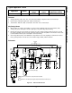
11. Current Sense: The MOSFET current is sensed
using an external sensing resistor for over-current
protection. If the CS pin voltage is higher than 0.8 V, the
over-current protection comparator generates a
protection signal. An internal RC filter of 40 kΩ and 8 pF
is included to filter sw itching noise.
12. Gate Driver Output: FAN7930C contains a single
totem-pole output stage designed for a direct drive of
the pow er MOSFET. The drive output is capable of up
to +500 / -800 mA peak current w ith a typical rise and
fall time of 50 ns w ith 1 nF load. The output voltage is
clamped to 13 V to protect the MOSFET gate even if the
V
CC
voltage is higher than 13 V.