
Data Sheet


FAN7888 — 3 Half-Bridge Gate-Drive IC
© 2008 Fairchild Semiconductor Corporation www.fairchildsemi.com
FAN7888 • Rev. 1.5 12
Application Information (Continued)
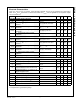
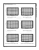
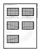
Figure 29. 120 Commutation Operation Waveforms for 3-Phase BLDC Motor Application
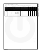
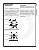
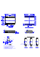
Switching Time Diagram
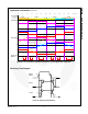
Figure 30. Switching Time Definition
Q1 (HIN1) Q3 (HIN2)
Q2 (LIN3)Q6 (LIN2)
Q5 (HIN3)Q5 (HIN3)
Q4 (LIN1)
-30 0 30 60 90 120 150 180 210 240 270 300 330
Elec
o
HIN / HO1,2,3
LIN / LO1,2,3
Input / Output
IU
IV
IW
Phase Current
VS1
VS2
VS3
Phase Voltage
Current Flow
Direction
U V W U V W U V W U V W U V W U V W
Phase Back EMF
50%
50%
t
ON(H)
t
R
t
OFF(H)
t
F
HIN1,2,3
/LIN1,2,3
HO1,2,3
10%
90%
10%
90%
10%
90%
10%
90%
t
ON(L)
t
OFF(L)
MT1 MT2
LO1,2,3