
Data Sheet


© 2009 Fairchild Semiconductor Corporation www.fairchildsemi.com
FAN7621 • Rev. 1.0.3 9
FAN7621 — PFM Controller for Half-Bridge Resonant Converters
Functional Description
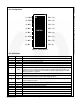
1. Basic Operation
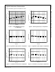
FAN7621 is designed to drive high-side and low-side
MOSFETs complementarily with 50% duty cycle. A fixed
dead time of 350ns is introduced between consecutive
transitions, as shown in Figure 16.
High-side
MOSFET
gate drive
Low-side
MOSFET
gate drve
Dead t im e
time
Figure 16. MOSFETs Gate Drive Signal
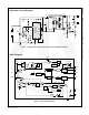
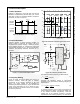
2. Internal Oscillator
FAN7621 employs a current-controlled oscillator, as
shown in Figure 17. Internally, the voltage of R
T
pin is
regulated at 2V and the charging / discharging current
for the oscillator capacitor, C
T
, is obtained by copying the
current flowing out of R
T
pin (I
CTC
) using a current mirror.
Therefore, the switching frequency increases as I
CTC
increases.
Figure 17. Current Controlled Oscillator
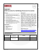
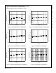
3. Frequency Setting
Figure 18 shows the typical voltage gain curve of a
resonant converter, where the gain is inversely
proportional to the switching frequency in the ZVS
region. The output voltage can be regulated by
modulating the switching frequency. Figure 19 shows the
typical circuit configuration for R
T
pin, where the opto-
coupler transistor is connected to the R
T
pin to modulate
the switching frequency.
0.6
0.8
1.0
1.2
1.4
1.6
1.8
Gain
140
150
60 70 80 90 100 110 120 130
Frequency (kHz)
f
min
f
normal
f
max
f
ISS
Soft-sta rt
Figure 18. Resonant Converter Typical Gain Curve
R
sense
FAN7621
V
CC
LV
CC
RT
CON
CS
SG PG
CTR
HV
CC
HO
LO
R
max
R
min
R
SS
C
SS
Figure 19. Frequency Control Circuit
The minimum switching frequency is determined as:
min
min
5.2
100( )
k
f
kHz
R
Ω
=×
(1)
Assuming the saturation voltage of opto-coupler
transistor is 0.2V, the maximum switching frequency is
determined as:
max
min max
5.2 4.68
( ) 100( )
kk
fkHz
RR
Ω
Ω
=+ ×
(2)
To prevent excessive inrush current and overshoot of
output voltage during startup, increase the voltage gain
of the resonant converter progressively. Since the
voltage gain of the resonant converter is inversely
proportional to the switching frequency, the soft-start is
I
CTC
+
-
+
-
3V
1V
-Q
Q
R
S
F/F
2I
CTC
V
REF
I
CTC
2V
+
-
Counte
r
(1/4)
R
T
8
Gate d
r
ive
C
T