
Data Sheet

FAN7529 Critical Conduction Mode PFC Controller
© 2006 Fairchild Semiconductor Corporation www.fairchildsemi.com
FAN7529 Rev. 1.0.2 5
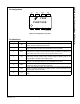
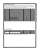
Electrical Characteristics
V
CC
= 14V and T
A
= -40°C~125°C unless otherwise specified.
Note:
2. These parameters, although guaranteed by design, are not tested in production.
Symbol Parameter Condition Min. Typ. Max. Unit
UNDER-VOLTAGE LOCKOUT SECTION
V
th(start)
Start Threshold Voltage V
CC
increasing 11 12 13 V
V
th(stop)
Stop Threshold Voltage V
CC
decreasing 7.5 8.5 9.5 V
HY
(uvlo)
UVLO Hysteresis 3.0 3.5 4.0 V
V
Z
Zener Voltage I
CC
= 20mA 20 22 24 V
SUPPLY CURRENT SECTION
I
st
Start-up Supply Current V
CC
= V
th(start)
- 0.2V 40 70 µA
I
CC
Operating Supply Current Output no switching 1.5 3.0 mA
I
dcc
Dynamic Operating Supply Current 50kHz, Cl=1nF 2.5 4.0 mA
I
CC(dis)
Operating Current at Disable V
inv
= 0V 20 65 95 µA
ERROR AMPLIFIER SECTION
V
ref1
Voltage Feedback Input Threshold1 T
A
= 25°C 2.465 2.500 2.535 V
ΔV
ref1
Line Regulation V
CC
= 14V ~ 20V 0.1 10.0 mV
ΔV
ref2
Temperature Stability of V
ref1
(2)
20 mV
I
b(ea)
Input Bias Current V
inv
= 1V ~ 4V -0.5 0.5 µA
I
source
Output Source Current V
inv
= V
ref1
- 0.1V -12 µA
I
sink
Output Sink Current V
inv
= V
ref1
+ 0.1V 12 µA
V
eao(H)
Output Upper Clamp Voltage V
inv
= V
ref1
- 0.1V 5.4 6.0 6.6 V
V
eao(Z)
Zero Duty Cycle Output Voltage 0.9 1.0 1.1 V
g
m
Transconductance
(2)
90 115 140 µmho
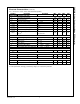
MAXIMUM ON-TIME SECTION
V
mot
Maximum On-Time Voltage R
mot
= 40.5kΩ 2.784 2.900 3.016 V
T
on(max)
Maximum On-Time Programming R
mot
= 40.5kΩ, T
A
= 25°C192429µs
CURRENT SENSE SECTION
V
CS(limit)
Current Sense Input Threshold
Voltage Limit
0.7 0.8 0.9 V
I
b(cs)
Input Bias Current V
CS
= 0V ~ 1V -1.0 -0.1 1.0 µA
t
d(cs)
Current Sense Delay to Output
(2)
dV/dt = 1V/100ns,
from 0V to 5V
350 500 ns