
Data Sheet

© 2009 Fairchild Semiconductor Corporation www.fairchildsemi.com
FAN5400 Family • Rev. 1.10 30
FAN5400 Family — USB-Compliant Single-Cell Li-Ion Switching Charger with USB-OTG Boost Regulator
I
2
C Interface
The FAN540X’s serial interface is compatible with Standard,
Fast, Fast Plus, and High-Speed Mode I
2
C-Bus®
specifications. The FAN540X’s SCL line is an input and its
SDA line is a bi-directional open-drain output; it can only pull
down the bus when active. The SDA line only pulls LOW
during data reads and when signaling ACK. All data is
shifted in MSB (bit 7) first.
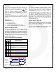
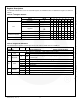
Slave Address
Table 20. I
2
C Slave Address Byte
Part Types
7
6
5
4
3
2
1
0
FAN5400–FAN5404
1
1
0
1
0
1
1
WR/
FAN5405
1
1
0
1
0
1
0
WR/
In hex notation, the slave address assumes a 0 LSB. The
hex slave address for the FAN5405 is D4h and is D6h for all
other parts in the family.
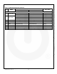
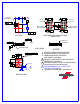
Bus Timing
As shown in Figure 45, data is normally transferred when
SCL is LOW. Data is clocked in on the rising edge of SCL.
Typically, data transitions shortly at or after the falling edge
of SCL to allow ample time for the data to set up before the
next SCL rising edge.
SCL
T
SU
T
H
SDA
Data change allowed
Figure 45. Data Transfer Timing
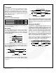
Each bus transaction begins and ends with SDA and SCL
HIGH. A transaction begins with a START condition, which is
defined as SDA transitioning from 1 to 0 with SCL HIGH, as
shown in Figure 46.
SCL
T
HD;STA
SDA
Slave Address
MS Bit
Figure 46. Start Bit
A transaction ends with a STOP condition, which is defined
as SDA transitioning from 0 to 1 with SCL HIGH, as shown
in Figure 47.
SCL
SDA
Slave Releases Master Drives
ACK(0) or
NACK(1)
t
HD;STO
Figure 47. Stop Bit
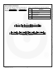
During a read from the FAN540X (Figure 50), the master
issues a Repeated Start after sending the register address
and before resending the slave address. The Repeated Start
is a 1-to-0 transition on SDA while SCL is HIGH, as shown in
Figure 48.
High-Speed (HS) Mode
The protocols for High-Speed (HS), Low-Speed (LS), and
Fast-Speed (FS) Modes are identical except the bus speed
for HS Mode is 3.4 MHz. HS Mode is entered when the bus
master sends the HS master code 00001XXX after a start
condition. The master code is sent in Fast or Fast Plus Mode
(less than 1MHz clock); slaves do not ACK this transmission.
The master then generates a repeated start condition
(Figure 48) that causes all slaves on the bus to switch to HS
Mode. The master then sends I
2
C packets, as described
above, using the HS Mode clock rate and timing.
The bus remains in HS Mode until a stop bit (Figure 47) is
sent by the master. While in HS Mode, packets are
separated by repeated start conditions (Figure 48).
SCL
SDA
ACK(0) or
NACK(1)
Slave Releases
SLADDR
MS Bit
t
HD;STA
t
SU;STA
Figure 48. Repeated Start Timing