
Data Sheet

© 2009 Fairchild Semiconductor Corporation www.fairchildsemi.com
FAN5400 Family • Rev. 1.10 26
FAN5400 Family — USB-Compliant Single-Cell Li-Ion Switching Charger with USB-OTG Boost Regulator
During the initial system startup, while the charger IC is
being programmed, the system current is limited to 325 mA
for 1ms during steps 4 and 5. This is the value of the soft-
start I
CHARGE
current used when I
INLIM
is set to No Limit.
If the system is powered up without a battery present, the
CV bit should be set. When a battery is inserted, the CV bit
is cleared.
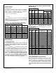
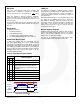
Charger Status / Fault Status
The STAT pin indicates the operating condition of the IC and
provides a fault indicator for interrupt driven systems.
Table 12. STAT Pin Function
EN_STAT
Charge State
STAT Pin
0
X
OPEN
X
Normal Conditions
OPEN
1
Charging
LOW
X
Fault
(Charging or Boost)
128s Pulse,
then OPEN
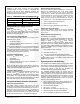
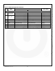
The FAULT bits (R0[2:0]) indicate the type of fault in Charge
Mode (see Table 13).
Table 13. Fault Status Bits During Charge Mode
Fault Bit
Fault Description
B2
B1
B0
0
0
0
Normal (No Fault)
0
0
1
VBUS OVP
0
1
0
Sleep Mode
0
1
1
Poor Input Source
1
0
0
Battery OVP
1
0
1
Thermal Shutdown
1
1
0
Timer Fault
1
1
1
No Battery
Charge Mode Control Bits
Setting either HZ_MODE or
CE
through I
2
C disables the
charger and puts the IC into High-Impedance Mode and
resets t
32S
. If V
BAT
< V
LOWV
while in High-Impedance Mode,
t
32S
begins running and, when it overflows, all registers
(except SAFETY) reset, which enables t
15MIN
charging on
versions with the 15-minute timer.
When t
15MIN
overflows, the IC sets the
CE
bit and the IC
enters High-Impedance Mode. If
CE
was set by t
15MIN
overflow, a new charge cycle can only be initiated through
I
2
C or VBUS POR.
Setting the RESET bit clears all registers. If HZ_MODE or
CE
bits were set when the RESET bit is set, these bits are
also cleared, but the t
32S
timer is not started, and the IC
remains in High-Impedance Mode.
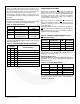
Table 14. FAN5403–FAN5405 DISABLE Pin and
CE
Bit Functionality
Charging
DISABLE Pin
CE
HZ_MODE
ENABLE
0
0
0
DISABLE
X
1
X
DISABLE
X
X
1
DISABLE
1
X
X
Raising the DISABLE pin stops t
32S
from advancing, but
does not reset it. If the DISABLE pin is raised during t
15MIN
charging, the t
15MIN
timer is reset.
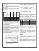
Operational Mode Control
OPA_MODE (REG1[0]) and the HZ_MODE (REG1[1]) bits in
conjunction with the FAULT state define the operational
mode of the charger.
Table 15. Operation Mode Control
HZ_MODE
OPA_MODE
FAULT
Operation Mode
0
0
0
Charge
0
X
1
Charge Configure
0
1
0
Boost
1
X
X
High Impedance
The IC resets the OPA_MODE bit whenever the boost is
deactivated, whether due to a fault or being disabled by
setting the HZ_MODE bit.