
Data Sheet

© 2009 Fairchild Semiconductor Corporation www.fairchildsemi.com
FAN5400 Family • Rev. 1.10 25
FAN5400 Family — USB-Compliant Single-Cell Li-Ion Switching Charger with USB-OTG Boost Regulator
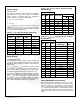
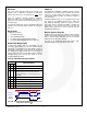
Additional
JA
data points, measured using the FAN540X
evaluation board, are given in Table 11 (measured with
T
A
=25°C). Note that as power dissipation increases, the
effective
JA
decreases due to the larger difference between
the die temperature and its ambient.
Table 11. FAN5400 Evaluation Board Measured
JA
Power (W)
JA
0.504
54°C / W
0.844
50°C / W
1.506
46°C / W
Charge Mode Input Supply Protection
Sleep Mode
When V
BUS
falls below V
BAT
+ V
SLP
, and V
BUS
is above
V
IN(MIN),
the IC enters Sleep Mode to prevent the battery from
draining into VBUS. During Sleep Mode, reverse current is
disabled by body switching Q1.
Input Supply Low-Voltage Detection
The IC continuously monitors VBUS during charging. If V
BUS
falls below V
IN(MIN)
, the IC:
1. Terminates charging
2. Pulses the STAT pin, sets the STAT bits to 11, and sets
the FAULT bits to 011.
If V
BUS
recovers above the V
IN(MIN)
rising threshold after time
t
INT
(about two seconds), the charging process is repeated.
This function prevents the USB power bus from collapsing or
oscillating when the IC is connected to a suspended USB
port or a low-current-capable OTG device.
Input Over-Voltage Detection
When the V
BUS
exceeds VBUS
OVP
, the IC:
1. Turns off Q3
2. Suspends charging
3. Sets the FAULT bits to 001, sets the STAT bits to 11,
and pulses the STAT pin.
When V
BUS
falls about 150 mV below VBUS
OVP
, the fault is
cleared and charging resumes after V
BUS
is revalidated (see
VBUS POR / Non-Compliant Charger Rejection).
VBUS Short While Charging
If VBUS is shorted with a very low impedance while the IC is
charging with I
INLIMIT
=100 mA, the IC may not meet
datasheet specifications until power is removed. To trigger
this condition, V
BUS
must be driven from 5 V to GND with a
high slew rate. Achieving this slew rate requires a 0 short
to the USB cable less than 10cm from the connector.
Charge Mode Battery Detection & Protection
VBAT Over-Voltage Protection
The OREG voltage regulation loop prevents V
BAT
from
overshooting the OREG voltage by more than 50 mV when
the battery is removed. When the PWM charger runs with no
battery, the TE bit is not set and a battery is inserted that is
charged to a voltage higher than V
OREG
; PWM pulses stop. If
no further pulses occur for 30 ms, the IC sets the FAULT bits
to 100, sets the STAT bits to 11, and pulses the STAT pin.
Battery Detection During Charging
The IC can detect the presence, absence, or removal of a
battery if the termination bit (TE) is set. During normal
charging, once V
BAT
is close to V
OREG
and the termination
charge current is detected, the IC terminates charging and
sets the STAT bits to 10. It then turns on a discharge current,
I
DETECT
, for t
DETECT
. If V
BAT
is still above V
OREG
– V
RCH
, the
battery is present and the IC sets the FAULT bits to 000. If
V
BAT
is below V
OREG
– V
RCH
, the battery is absent and the IC:
1. Sets the registers to their default values.
2. Sets the FAULT bits to 111.
3. Resumes charging with default values after t
INT
.
Battery Short-Circuit Protection
If the battery voltage is below the short-circuit threshold
(V
SHORT
); a linear current source, I
SHORT
, supplies V
BAT
until
V
BAT
> V
SHORT
.
Battery Detection During Power-up
For FAN5400 and FAN5403
At VBUS POR, a 5 k load is applied to VBAT for 500 ms to
discharge any residual system capacitance in case the
battery is absent. If V
BAT
< V
SHORT
, linear charging
commences. When V
BAT
rises above V
SHORT
, PWM charging
proceeds with the float voltage (OREG) temporarily set to
4 V. If the battery voltage exceeds 3.7 V within 32 ms of the
beginning of PWM charging, the battery is absent. If battery
absent is detected:
1. High-Impedance Mode is entered.
2. FAULT bits are set to 111.
3. The t
15MIN
timer is disabled until VBUS is removed.
If V
BAT
remains below 3.7 V during the initial 32 ms period,
the float voltage returns to the OREG register setting and
PWM charging continues.
System Operation with No Battery
The FAN5402 and FAN5405 continue charging after VBUS
POR with the default parameters, regulating the V
BAT
line to
3.54 V until the host processor issues commands or the 15-
minute timer expires. In this way, the FAN5402 and
FAN5405 can start the system without a battery.
The FAN540X soft-start function can interfere with the
system supply with battery absent. The soft-start activates
whenever V
OREG
, I
INLIM
, or I
OCHARGE
are set from a lower to
higher value. During soft-start, the I
IN
limit drops to 100 mA
for about 1 ms unless I
INLIM
is set to 11 (no limit). This could
cause the system processor to fail to start. To avoid this
behavior, use the following sequence.
1. Set the OTG pin HIGH. When VBUS is plugged in, I
INLIM
is set to 500 mA until the system processor powers up
and can set parameters through I
2
C.
2. Program the Safety Register.
3. Set I
INLIM
to 11 (no limit).
4. Set OREG to the desired value (typically 4.18).
5. Reset the IOLEVEL bit, then set IOCHARGE.
6. Set I
INLIM
to 500mA if a USB source is connected.