
Data Sheet

July 2015
© 2009 Fairchild Semiconductor Corporation www.fairchildsemi.com
FAN5400 Family • Rev. 1.10
FAN5400 Family — USB-Compliant Single-Cell Li-Ion Switching Charger with USB-OTG Boost Regulator
FAN5400 / FAN5401 / FAN5402 / FAN5403 / FAN5404 / FAN5405
USB-Compliant Single-Cell Li-Ion Switching Charger with
USB-OTG Boost Regulator
Features
Fully Integrated, High-Efficiency Charger for Single-Cell
Li-Ion and Li-Polymer Battery Packs
Faster Charging than Linear
Charge Voltage Accuracy: 0.5% at 25°C
1% from 0 to 125°C
5% Input Current Regulation Accuracy
5% Charge Current Regulation Accuracy
20 V Absolute Maximum Input Voltage
6 V Maximum Input Operating Voltage
1.25 A Maximum Charge Rate
Programmable through High-Speed I
2
C Interface
(3.4 Mb/s) with Fast Mode Plus Compatibility
– Input Current
– Fast-Charge / Termination Current
– Charger Voltage
– Termination Enable
3 MHz Synchronous Buck PWM Controller with Wide
Duty Cycle Range
Small Footprint 1 H External Inductor
Safety Timer with Reset Control
1.8 V Regulated Output from VBUS for Auxiliary Circuits
Weak Input Sources Accommodated by Reducing
Charging Current to Maintain Minimum VBUS Voltage
Low Reverse Leakage to Prevent Battery Drain to VBUS
5 V, 300 mA Boost Mode for USB OTG for 2.5 to 4.5 V
Battery Input
Applications
Cell Phones, Smart Phones, PDAs
Tablet, Portable Media Players
Gaming Device, Digital Cameras
Description
The FAN5400 family (FAN540x) combines a highly integrated
switch-mode charger, to minimize single-cell Lithium-ion
(Li-ion) charging time from a USB power source, and a boost
regulator to power a USB peripheral from the battery.
The charging parameters and operating modes are
programmable through an I
2
C Interface that operates up to
3.4 Mbps. The charger and boost regulator circuits switch at
3 MHz to minimize the size of external passive components.
The FAN540X provides battery charging in three phases:
conditioning, constant current, and constant voltage.
To ensure USB compliance and minimize charging time, the
input current is limited to the value set through the I
2
C host.
Charge termination is determined by a programmable
minimum current level. A safety timer with reset control
provides a safety backup for the I
2
C host.
The integrated circuit (IC) automatically restarts the charge
cycle when the battery falls below an internal threshold. If the
input source is removed, the IC enters a high-impedance
mode with leakage from the battery to the input prevented.
Charge status is reported back to the host through the I
2
C
port. Charge current is reduced when the die temperature
reaches 120°C.
The FAN540X can operate as a boost regulator on
command from the system. The boost regulator includes a
soft-start that limits inrush current from the battery.
The FAN540X is available in a 1.96 x 1.87 mm, 20-bump,
0.4 mm pitch, WLCSP package.
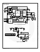
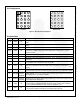
FAN540X
SW
PGND
C
OUT
L1
VBAT
+
Battery
CSIN
R
SENSE
68m
1H
C
BAT
SYSTEM
LOAD
0.1F
VBUS
1F
PMID
4.7F
SDA
SCL
OTG/USB#
C
REG
1F
VREG
STAT
10F
DISABLE
C
BUS
C
MID
Figure 1. Typical Application (FAN5403-05 Pin Out)
All trademarks are the property of their respective owners.