
Data Sheet

© 2009 Fairchild Semiconductor Corporation www.fairchildsemi.com
FAN5400 Family • Rev. 1.10 18
FAN5400 Family — USB-Compliant Single-Cell Li-Ion Switching Charger with USB-OTG Boost Regulator
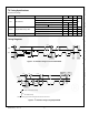
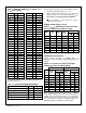
Table 3. OREG Bits (OREG[7:2]) vs. Charger V
OUT
(V
OREG
) Float Voltage
Decimal
Hex
VOREG
Decimal
Hex
VOREG
0
00
3.50
32
20
4.14
1
01
3.52
33
21
4.16
2
02
3.54
34
22
4.18
3
03
3.56
35
23
4.20
4
04
3.58
36
24
4.22
5
05
3.60
37
25
4.24
6
06
3.62
38
26
4.26
7
07
3.64
39
27
4.28
8
08
3.66
40
28
4.30
9
09
3.68
41
29
4.32
10
0A
3.70
42
2A
4.34
11
0B
3.72
43
2B
4.36
12
0C
3.74
44
2C
4.38
13
0D
3.76
45
2D
4.40
14
0E
3.78
46
2E
4.42
15
0F
3.80
47
2F
4.44
16
10
3.82
48
30
4.44
17
11
3.84
49
31
4.44
18
12
3.86
50
32
4.44
19
13
3.88
51
33
4.44
20
14
3.90
52
34
4.44
21
15
3.92
53
35
4.44
22
16
3.94
54
36
4.44
23
17
3.96
55
37
4.44
24
18
3.98
56
38
4.44
25
19
4.00
57
39
4.44
26
1A
4.02
58
3A
4.44
27
1B
4.04
59
3B
4.44
28
1C
4.06
60
3C
4.44
29
1D
4.08
61
3D
4.44
30
1E
4.10
62
3E
4.44
The following charging parameters can be programmed by
the host through I
2
C:
Table 4. Programmable Charging Parameters
Parameter
Name
Register
Output Voltage Regulation
V
OREG
REG2[7:2]
Battery Charging Current Limit
I
OCHRG
REG4[6:4]
Input Current Limit
I
INLIM
REG1[7:6]
Charge Termination Limit
I
TERM
REG4[2:0]
Weak Battery Voltage
V
LOWV
REG1[5:4]
A new charge cycle begins when one of the following occurs:
The battery voltage falls below V
OREG
- V
RCH
VBUS Power On Reset (POR) clears and the battery
voltage is below the weak battery threshold (V
LOWV
).
This occurs for all versions except the FAN5401.
CE
or HZ_MODE is reset through I
2
C write to
CONTROL1 (R1) register.
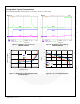
Charge Current Limit (I
OCHARGE
)
Table 5. I
OCHARGE
(REG4 [6:4]) Current as Function
of I
OCHARGE
Bits and R
SENSE
Resistor Values
DEC
BIN
HEX
V
RSENSE
(mV)
I
OCHARGE
(mA)
68 m
100 m
0
000
00
37.4
550
374
1
001
01
44.2
650
442
2
010
02
51.0
750
510
3
011
03
57.8
850
578
4
100
04
64.6
950
646
5
101
05
71.4
1050
714
6
110
06
78.2
1150
782
7
111
07
85.0
1250
850
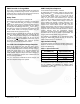
Termination Current Limit
Current charge termination is enabled when TE
(REG1[3])=1. Typical termination current values are given in
Table 6.
Table 6. I
TERM
Current as Function of I
TERM
Bits
(REG4[2:0]) and R
SENSE
Resistor Values
FAN5400 - FAN5402
FAN5403 - FAN5405
I
TERM
V
RSENSE
(mV)
I
TERM
(mA)
V
RSENSE
(mV)
I
TERM
(mA)
68 m
100 m
68 m
100 m
0
3.4
50
34
3.3
49
33
1
6.8
100
68
6.6
97
66
2
10.2
150
102
9.9
146
99
3
13.6
200
136
13.2
194
132
4
17.0
250
170
16.5
243
165
5
20.4
300
204
19.8
291
198
6
23.8
350
238
23.1
340
231
7
27.2
400
272
26.4
388
264
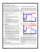
When the charge current falls below I
TERM
for a period of
32 ms; PWM charging stops and the STAT bits change to
READY (00) for about 500 ms while the IC determines
whether the battery and charging source are still connected.
The STAT bits then change to CHARGE DONE (10),
provided the battery and charger are still connected.