
Data Sheet

© 2009 Fairchild Semiconductor Corporation www.fairchildsemi.com
FAN5400 Family • Rev. 1.10 17
FAN5400 Family — USB-Compliant Single-Cell Li-Ion Switching Charger with USB-OTG Boost Regulator
Circuit Description / Overview
When charging batteries with a current-limited input source,
such as USB, a switching charger’s high efficiency over a
wide range of output voltages minimizes charging time.
FAN540X combines a highly integrated synchronous buck
regulator for charging with a synchronous boost regulator,
which can supply 5 V to USB On-The-Go (OTG) peripherals.
The regulator employs synchronous rectification for both the
charger and boost regulators to maintain high efficiency over
a wide range of battery voltages and charge states.
The FAN540X has three operating modes:
1. Charge Mode:
Charges a single-cell Li-ion or Li-polymer battery.
2. Boost Mode:
Provides 5 V power to USB-OTG with an integrated
synchronous rectification boost regulator using the
battery as input.
3. High-Impedance Mode:
Both the boost and charging circuits are OFF in this
mode. Current flow from VBUS to the battery or from the
battery to VBUS is blocked in this mode. This mode
consumes very little current from VBUS or the battery.
Note: Default settings are denoted by bold typeface.
Charge Mode
In Charge Mode, FAN540X employs four regulation loops:
1. Input Current: Limits the amount of current drawn from
VBUS. This current is sensed internally and can be
programmed through the I
2
C interface.
2. Charging Current: Limits the maximum charging current.
This current is sensed using an external R
SENSE
resistor.
3. Charge Voltage: The regulator is restricted from
exceeding this voltage. As the internal battery voltage
rises, the battery’s internal impedance and R
SENSE
work
in conjunction with the charge voltage regulation to
decrease the amount of current flowing to the battery.
Battery charging is completed when the voltage across
R
SENSE
drops below the I
TERM
threshold.
4. Temperature: If the IC’s junction temperature reaches
120°C, charge current is continuously reduced until the
IC’s temperature stabilizes at 120°C.
In addition, the FAN5403-05 employ an additional loop to
limit the amount of drop on VBUS to a programmable voltage
(V
SP
) to accommodate “special chargers” that limit current to
a lower current than might be available from a “normal” USB
wall charger.
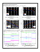
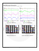
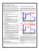
Battery Charging Curve
If the battery voltage is below V
SHORT
, a linear current source
pre-charges the battery until V
BAT
reaches V
SHORT
. The PWM
charging circuit is then started and the battery is charged
with a constant current if sufficient input power is available.
The current slew rate is limited to prevent overshoot.
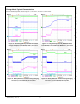
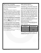
The FAN540X is designed to work with a current-limited
input source at VBUS. During the current regulation phase of
charging, I
INLIM
or the programmed charging current limits the
amount of current available to charge the battery and power
the system. The effect of I
INLIM
on I
CHARGE
can be seen in
Figure 36.
V
OREG
V
B
A
T
I
SHORT
I
CHARGE
PRE-
CHARGE
CURRENT REGULATION
VOLTAGE
REGULATION
I
OCHARGE
V
SHORT
I
TERM
Figure 35. Charge Curve, I
CHARGE
Not Limited by I
INLIM
V
OREG
I
SHORT
I
C
H
A
R
G
E
PRE-
CHARGE
CURRENT REGULATION
VOLTAGE
REGULATION
V
SHORT
I
TERM
V
B
A
T
Figure 36. Charge Curve, I
INLIM
Limits I
CHARGE
Assuming that V
OREG
is programmed to the cell’s fully
charged “float” voltage, the current that the battery accepts
with the PWM regulator limiting its output (sensed at VBAT)
to V
OREG
declines, and the charger enters the voltage
regulation phase of charging. When the current declines to
the programmed I
TERM
value, the charge cycle is complete.
Charge current termination can be disabled by resetting the
TE bit (REG1[3]).
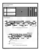
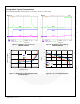
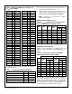
The charger output or “float” voltage can be programmed by
the OREG bits from 3.5 V to 4.44 V in 20 mV increments, as
shown in Table 3.