
Data Sheet


www.onsemi.com
7
FAN4010 — High-Side Current Sensor
Application Information
Detailed Description
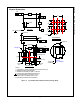
The FAN4010 measures the voltage drop (V
SENSE
)
across an external sense resistor in the high-voltage
side of the circuit. V
SENSE
is converted to a linear current
via an internal operational amplifier and precision 100 Ω
resistor. The value of this current is V
SENSE
/100 Ω
(internal). Output current flow s from the I
OUT
pin to an
external resistor R
OUT
to generate an output voltage
proportional to the current flow ing to the load.
Use the follow ing equations to scale a load current to an
output voltage:
V
= I
• R
(1)
V
= 0.01 × V
× R
(2)
Figure 13. Functional Circuit
Selecting R
SENSE
Selection of R
SENSE
is a balance betw een desired
accuracy and allow able voltage loss. Although the
FAN4010 is optimized for high accuracy w ith low V
SENSE
values, a larger R
SENSE
value provides additional
accuracy. How ever, larger values of R
SENSE
create a
larger voltage drop, reducing the effective voltage
available to the load. This can be troublesome in low -
voltage applications. Because of this, the maximum
expected load current and allow able load voltage should
be w ell understood. Although higher values of V
SENSE
can be used, R
SENSE
should be chosen to satisfy the
follow ing condition:
10mV <
< 200
(3)
For low -cost applications w here accuracy is not as
important, a portion of the printed circuit board (PCB)
trace can be used as an R
SENSE
resistor. Figure 14
show s an example of this configuration. The resistivity
of a 0.1-inch w ide trace of tw o-ounce copper is about
30 mΩ/ft. Unfortunately, the resistance temperature
coefficient is relatively large (approximately 0.4%/°C), so
systems w ith a w ide temperature range may need to
compensate for this effect. Additionally, self heating due
to load currents introduces a nonlinearity error. Care
must be taken not to exceed the maximum pow er
dissipation of the copper trace.
Figure 14. Using PCB Trace for R
SENSE
Selecting R
OUT
R
OUT
can be chosen to obtain the output voltage range
required for the particular dow nstream application. For
example, if the output of the FAN4010 is intended to
drive an analog-to-digital convertor (ADC), R
OUT
should
be chosen such that the expected full-scale output
current produces an input voltage that matches the input
range of the ADC. For instance, if expected loading
current ranges from 0 to 1 A, an R
SENSE
resistor of 1 Ω
produces an output current that ranges from 0 to 10 mA .
If the input voltage range of the ADC is 0 to 2 V, an R
OUT
value of 200 Ω should be used. The input voltage and
full-scale output current (I
OUT_FS
) needs to be taken into
account w hen setting up the output range. To ensure
sufficient operating headroom, choose:
R
I
such that
V
V
–
R
I
> 1.6
(4)
Output current accuracy for the recommended V
SENSE
betw een 10 mV and 200 mV are typically better than
1%. As a result, the absolute output voltage accuracy is
dependent on the precision of the output resistor.
Make sure the input impedance of the circuit connected
to V
OUT
is much higher than R
OUT
to ensure accurate
V
OUT
values.
Since the FAN4010 provides a trans-impedance
function, it is suitable for applications involving current
rather than voltage sensing.
R
OUT
3
6
1
I
OUT
Load
V
IN
V
sense
V
OUT
100
R
sense
+
-
V
IN
R
Load
R
SENSE
INPU
T LOAD
0.3in COPPER
0.3in COPPER
0.1in COPPER
R
OUT
2
3 4
I
OUT
LoadV
IN
1
GND
NC
V
OUT
6
5
NC