
Data Sheet


www.onsemi.com
2
FAN3121 / FAN3122 — Single 9-A High-Speed, Low-Side Gate Driver
Ordering Information
Part Number
Logic
Input
Threshold
Package
Packing
Method
Quantity
per Reel
FAN3121CMPX
Inverting
Channels +
Enable
CMOS
3x3 mm MLP-8
Tape & Reel
3,000
FAN3121CMX
SOIC-8
Tape & Reel
2,500
FAN3121CMX-F085
(1)
SOIC-8
Tape & Reel
2,500
FAN3121TMPX
TTL
3x3 mm MLP-8
Tape & Reel
3,000
FAN3121TMX
SOIC-8
Tape & Reel
2,500
FAN3121TMX-F085
(1)
SOIC-8
Tape & Reel
2,500
FAN3122CMPX
Non-Inverting
Channels +
Enable
CMOS
3x3 mm MLP-8
Tape & Reel
3,000
FAN3122CMX
SOIC-8
Tape & Reel
2,500
FAN3122CMX-F085
(1)
SOIC-8
Tape & Reel
2,500
FAN3122TMPX
TTL
3x3 mm MLP-8
Tape & Reel
3,000
FAN3122TMX
SOIC-8
Tape & Reel
2,500
FAN3122TMX-F085
(1)
SOIC-8
Tape & Reel
2,500
Note:
1. Qualified to AEC-Q100.
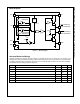
Package Outlines
1
8
7
2
6
3
4
5
2
3
8
6
1
4
7
5
Figure 3. 3x3 mm MLP-8 (Top View)
Figure 4. SOIC-8 (Top View)
Thermal Characteristics
(2)
Package
Θ
JL
(3)
Θ
JT
(4)
Θ
JA
(5)
Ψ
JB
(6)
Ψ
JT
(7)
Units
8-Lead 3x3 mm Molded Leadless Package (MLP)
1.2
64
42
2.8
0.7
°C/W
8-Pin Small Outline Integrated Circuit (SOIC)
38
29
87
41
2.3
°C/W
Notes:
2. Estimates derived from thermal simulation; actual values depend on the application.
3. Theta_JL (Θ
JL
): Thermal resistance between the semiconductor junction and the bottom surface of all the leads
(including any thermal pad) that are typically soldered to a PCB.
4. Theta_JT (Θ
JT
): Thermal resistance between the semiconductor junction and the top surface of the package,
assuming it is held at a uniform temperature by a top-side heatsink.
5. Theta_JA (Θ
JA
): Thermal resistance between junction and ambient, dependent on the PCB design, heat sinking,
and airflow. The value given is for natural convection with no heatsink, as specified in JEDEC standards
JESD51-2, JESD51-5, and JESD51-7, as appropriate.
6. Psi_JB (Ψ
JB
): Thermal characterization parameter providing correlation between semiconductor junction
temperature and an application circuit board reference point for the thermal environment defined in Note 5. For
the MLP-8 package, the board reference is defined as the PCB copper connected to the thermal pad and
protruding from either end of the package. For the SOIC-8 package, the board reference is defined as the PCB
copper adjacent to pin 6.
7. Psi_JT (Ψ
JT
): Thermal characterization parameter providing correlation between the semiconductor junction
temperature and the center of the top of the package for the thermal environment defined in Note 5.