
User Manual


Main Tower
A. Stepper Motor—This motor helps control attached rotary axes.
B. Mainboard—This circuit board works with your software to control the laser.
C. Mainboard Power Supply—This device draws 0.5A to convert standard electricity to 5V 3A power for the mainboard.
D. Laser Power Supply—This device draws 6.8A to convert standard electricity to 24V 14.6A power for the fiber laser
source.
E. Galvanometer Power Supply—This device draws 2.5A to convert standard electricity to 15V 2A power for the scanning
lens.
F. Fiber Laser Source (Inside Casing)—This component creates the laser beam and transfers it to the fiber optic pathway
to the scanning lens.
4
A
B
C
D
E
B
C
E
D
F
A
B
C
E
D
F
A
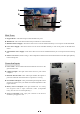
Connection Inputs
A. Laser Cable—This transmits the laser beam from its source to the
galvonometric lens.
B. USB Cord Input—This port connects the device to your control
computer.
C. Interlock & Fan Cable—This cable input enables the option to
power the interlock and exhaust fan of a protective covering.
D. Foot Pedal Cord Input—This port enables optional pedal control
of laser activation to free your hands for manual adjustment of the
target material.
E. Rotary Axis Cord Input—This port enables use of a rotary
axis engraver with a 4-pin connection cable. (Compatible
rotary axis devices are sold separately.)
F. Power Cord Input—This 3-pin port connects to the device's
standard 3-prong power cord.