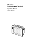
NT-series Programmable Terminal Operation Manual Cat. No.
OMRON Product References All OMRON products are capitalized in this manual. The word “Unit” is also capitalized when it refers to an OMRON product, regardless of whether or not it appears in the proper name of the product. The abbreviation “Ch,” which appears in some displays and on some OMRON products, often means “word” and is abbreviated “Wd” in documentation in this sense. The abbreviation “PC” means Programmable Controller and is not used as an abbreviation for anything else.
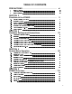
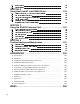
TABLE OF CONTENTS PRECAUTIONS . . . . . . . . . . . . . . . . . . . . . . . . . . . . . . . . . . . . . . xi SECTION 2 Functions of the NT600S . . . . . . . . . . . . . . . . . . . . . . . . . . . . . " ' - ! # $ % & $ ! ! ( ) * $ ## + $ ) % SECTION 3 Hardware Settings and Connections .
' ' 5 ( 4 ( # % 5 " SECTION 6 Using Host Link/NT Link/C200H Direct . . . . . . . . . . . . . . . . 153 " ' . / 0 8 / 08$ . & 6 # + ) ( / # ; ( 4 ( ; # % $ ( % ( $ 1& # % ( % 3 '" " 5 , ,- SECTION 7 Using the RS-232C Interface Unit . . . . . . . . . . . . . . . . . . . . .
About this Manual: This manual describes the installation and operation of the NT600S Programmable Terminals (PTs) and includes the sections described below. Further information is provided in manuals on the Host Interface Units and Support Tool. Refer to the list in Section 1 Introduction. Please read this manual completely and be sure you understand the information provide before attempting to install and operate a Programmable Terminal.
Manuals: The related manuals are indicated below. The symbol at the end of the manual number is the revision history symbol. Operating the Programmable terminal and Communicating with the Host NT600S Programmable Terminal Operation Manual V022-E1- (this manual) This operation manual is the manual for the NT600S itself. The NT600S is a unit which integrates a programmable terminal body and host interface unit.
PRECAUTIONS ( ? % % ( % ## + #
1 Intended Audience This manual is intended for the following personnel, who must also have knowledge of electrical systems (an electrical engineer or the equivalent). 2 Personnel in charge of installing FA systems. Personnel in charge of designing FA systems. Personnel in charge of managing FA systems and facilities. General Precautions The user must operate the product according to the performance specifications described in the operation manuals.
Safety Precautions (continued) WARNING: Do not attempt to take the NT600S apart and do not touch any internal parts while the power is being supplied. Doing either of these may result in electrical shock. Switch off the power before replacing the backlight, or you could sustain an electric shock. Caution: Select a proper location referring to Appendix D Installation Environment (page 262). Always switch OFF the power before assembling equipment or connecting cables.
Safety Precautions (continued) The cable’s tensile load is 30 N. Do not subject it to loads greater than this. Otherwise a discontinuity may occur, causing operation to fail.
Safety Precautions (continued) Do not disassemble for repairs or modification, or the product may malfunction. The disposal of the NT600S (and used backlights) may be regulated by national or local authorities. Dispose of them in accordance with the laws and regulations of the relevant country and local authority. Never short the + and -- terminals of the battery. Do not recharge, take apart, deform, or discharge it into open flame.
SECTION 2 Functions of the NT600S NT600S is a new programmable terminal (PT) which incorporates a host interface unit and a RS-232C interface unit in a programmable terminal body. It can be easily installed and used. This section gives the operation examples and characteristics of the NT600S so that you will understand the applications of the NT600S. 2-1 2-2 2-3 2-4 2-5 2-6 2-7 Role and Operation of NT600S . . . . . . . . . . . . . . . . . . . . . . . . . . . . . . . . . . . . . . . . . . . . . . .
2-1 Section 1-1 Role and Operation of NT600S NT600S is a programmable terminal used to display and transmit the information in an FA site. The following gives a general description of the role and operation of the NT600S for those who use a programmable terminal (PT) for the first time. Production Line Status Monitoring The NT600S displays real-time information about the system and equipment operating status, etc.
2-1-1 Section 1-1 Operations of NT600S Displays Screens The information to be displayed (screen data) can be created on a computer by using support tools and stored in the NT600S. The screen data can be displayed on the NT600S in response to the instructions from a PC/Host or touch switch operation. Host PC The screen data designated by instructions from PC/Host or touch switch operation is displayed.
2-2 Section 1-2 Functions of NT600S The NT600S has the following features which are different from those of existing NT600M; 2-2-1 Features Downsized Body The NT600S has thin depth (64 mm or less in the panel) in the NT series. The width is shorter by 50 mm, maintaining the existing display area. The tool connectors are located at the rear of the unit. The communication cable connectors are housed in the unit so that they do not protrude from the unit.
Section 1-2 Availability of the C200H Direct Communication Function The C200H direct communication function can be used if the C200H interface unit (NT-LB122), which must be purchased separately, is mounted to the NT600S. Touch Switch Operation The System Menu can be displayed by using the touch switches located in four corners of the screen. Compatibility with NT600M Existing screen data, user programs, and support tools are compatible.
2-2-2 Section 1-2 Principal Functions of NT600S Functions Related to the Data Display Character display Characters of various sizes can be displayed. Characters can flash or be highlighted. Figure display Straight lines, circles, and other graphic figures can be displayed. Memory data display Contents of the character-string memory table and the numeral memory table can be displayed. The memory table contents can be changed from the PC/Host.
2-2-3 Section 1-2 Comparison between NT600S and NT600M The NT600S is a unitary PT which incorporates a system ROM, screen memory, and a host I/F unit (host link, NT link, and RS-232C) as the standard equipment in one body. The NT600S has the following features which are different from those of existing NT600M; Function NT600S-ST121/-ST211-EV NT600M-DT122 Communication Host link/NT link/NT Link (1:1, 1:N)/RS-232C Host I/F units are required. incorporated.
2-2-4 Section 1-2 Differences Between Existing Models and NT600S-ST121/ST211-EV3 Difference between direct connection Ver.4 and Ver.5 Ver.5 of the direct connection function has the following additional functions in comparison with Ver.4. “Thumbwheel” type setting possible with the numeral setting function. Upper and lower limit check can be set with the numeral setting function.
2-2-5 Section 1-2 Displays The NT600S can display various kinds of elements such as characters, numeric value, lamps, touch switches, and bar graphs on a screen. The screen data displayed on the NT600S are created by using support tools on a computer. Touch switches Characters (character string) Characters (text) Stop Line A Machine name Production qty.
2-3 Section 1-3 System Configuration This section gives the basic configuration of a system which uses an NT600S. Refer to the manual for individual device for information on the equipment other than the NT600S in the system. Reference The following four communication methods are supported for communications between the NT600S and PC/Host: host link, NT link, RS-232C, and C200H direct.
Section 1-3 Reference Host link and NT link (1:1) communications can be performed with RS-422A by using an RS-232C/RS-422A converter unit (type NT-AL001), but communications with RS-485 are not possible. For details on the wiring for RS-422A, refer to “Appendix F Connecting to an RS-232C/RS-422A Converter Unit” (page 275 of the appendix). NT Link (1:N) Systems When NT600S is connected to a PC in a 1:N connection, use an RS-232C cable and RS-422A/485 cables.
Section 1-3 When using the C200H Direct Communication Function Use an I/O connecting cable for the connection to the PC, and an RS-232C cable for connection to the Host. PC made by OMRON Controls the NT600S as required for machine control, line monitoring, etc.
2-4 Section 1-4 Direct Connection Function The communication method applied between the NT600S and the PC is either a host link or NT link or C200H or RS232C direct. The following deals with the ”direct access” available when a host link, NT link, or C200H direct is used, and the communication with a PC.
2-4-1 Section 1-4 What is the NT Link (1:N) The NT link uses the direct connection function and can execute high-speed communications with the CPU units (with built-in host link) of the CPM1, CQM1, C200HS, C200HX/HG/HE, or CVM1/CV series. When using the NT600S in an NT link, two communications modes are possible: a single NT600S can be connected to one PC (1:1 NT link), or alternatively, up to eight NT600S units can be connected to a single PC port (1:N NT link).
2-4-2 Section 1-4 C200H Direct Communication H, C200H, and C200H direct communication allows communication with C C200HS CPU units by using the “direct connection” function. Advantage of C200H Direct Communication Since an I/O connecting cable is used for connection to each CPU unit, highspeed communication is possible.
2-5 Section 1-5 Functions of the Allocated Bits and Words Elements displayed on the NT600S and the NT600S status can be allocated to the bits and words of the PC. By changing the contents of the bits and words, the NT600S can be controlled by the PC. It is also possible to send data to the PC by pressing the touch switches on the NT600S. Controlling the NT600S by a PC The following NT600S functions can be controlled by a PC.
Section 1-5 Touch switches Allocation destination: Bit Touch switch #12 Bit 009012 NT600S PC Bit 009012: ON The lamp comes on (flashes) when the PC’s control bit is ON (1) and goes off when it is OFF (0). While the touch switch is pressed, the PC’s notification bit turns ON (1), and when it is released, the bit turns OFF (0).
Section 1-5 Functions of the PT Status Control Area (PC to NT600S) The “PT status control area” is used to control the NT600S status. When data is written to this area in the PC, the NT600S reads the contents and operates according to the contents. [Example of the PT status control area application] When data is written to the PT status control area, the NT600S will operate as given below.
!"#" 2-6 Section 1-6 Communications by RS-232C Control of the NT600S by a Host is executed by two kinds of commands supported by the RS-232C interface which is built into the NT600S. Operation commands Operation commands are used to control the display and status of the running NT600S as well as to notify information. Screen display, data writing, data inquiries, etc. Notification of the NT600S operation contents to the Host.
2-7 Section 1-7 Before Operating Follow the procedure given below to start the system of the NT600S. When using Host Link/NT Link/RS-232C Host PC Check and change the PC settings. For the host link, refer to page 31 and the manuals for the host link unit and peripheral tools. For the NT link (1:1), refer to page 43. For the NT link (1:N), refer to page 47.
Section 1-7 Refer to the following manuals for the equipment and software.
SECTION 3 Hardware Settings and Connections This section describes the settings of the NT600S, connections to a PC/Host, and other hardware settings. 3-1 3-2 3-3 3-4 3-5 3-6 3-7 3-8 Description of Parts and Settings . . . . . . . . . . . . . . . . . . . . . . . . . . . . . . . . . . . . . . . . . . . . . . 3-1-1 Description of Parts . . . . . . . . . . . . . . . . . . . . . . . . . . . . . . . . . . . . . . . . . . . . . . . . . . . . 3-1-2 DIP Switch Settings . . . . . . . . . . . . . . . . . . . .
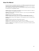
3-1 $ Section 2-1 Description of Parts and Settings Before getting to the operation, confirm the names and functions of parts. Also set the DIP switches on the NT600S. Caution On unpacking the NT600S, check its external appearance and confirm that there is no damage. Also confirm that there is no abnormal noise on shaking the unit lightly. The product may malfunction if it is damaged. 3-1-1 Description of Parts Front View POWER LED Lit when the power is supplied.
$ Section 2-1 Rear View DIP switch (SW2) Set various system statuses with these switches. Lid of CFL case The backlight unit and battery mounting holder are installed underneath this lid. Contrast control (ST121 only) Use a fine flat-blade screwdriver. Turn clockwise to increase the brightness. Host interface unit connector Connect the cable from the host interface unit here. 24VDC + Reset switch (SW1) Grounding terminal Initializes the NT600S statuses.
3-1-2 $ Section 2-1 DIP Switch Settings Set the NT600S operation status with the DIP switches located in the bottom right corner on the rear side of the body. Switch # SW2-1 SW2-2 ON The NT600S will start in a special RUN mode in which the screen data memory is initialized. When it is started, the memory initialization menu will be displayed. For the initialization procedure, refer to Section 4-4 Initializing Memory (page 72). [OFF] The NT600S will start in normal RUN mode.
% 3-2 Section 2-2 Installation Install the NT600S to the operation panel and connect the power to the NT600S as described below. Caution Select a proper location referring to Appendix D Installation Environment (page 262). Always switch OFF the power before assembling equipment or connecting cables. Otherwise you could sustain an electric shock or equipment could be damaged. 3-2-1 Installation to the Operation Panel The NT600S can be flush mounted to an operation panel.
% 3-2-2 Section 2-2 Power Supply Connection Connect a 24 VDC power supply to the power input terminals. Note Use 2 mm2 or thicker wires to prevent voltage drop. Twist the wires together for wiring. Make sure you connect the power supply wires with the correct polarity. Do not connect AC power to the DC terminals. If the power supply voltage does not conform to the stipulated rating, it could destroy the terminal or burn internal circuits.
% Section 2-2 Caution Fit crimp-style terminals to the power cable. Connecting the wires of the cable to the terminal block directly after merely twisting them together could cause fire and other hazards. Fork type 7 mm or less Round type 7 mm or less [Recommended terminals] Type Type (fork type) (round type) Maker 3-2-3 Japan Solderless Terminal MFG 2-YS3A 2-3.5 Fuji Terminal 2-YAS3.5 V2-S3.5 Nichifu Terminal 2Y-3.5 2-3.5 Applicable Wire (stranded wire) 1.04 to 2.
3-3 Section 2-3 Connecting to the Support Tool Connect the NT600S to a computer with an RS-232C cable to transfer the screen data created by using a support tool to the NT600S. In other than C200H direct communications, it is impossible to connect a computer and the Host that are used to run the support tool at the same time. Connect a computer only for transferring the screen data. Communication conditions Communication conditions are set when a support tool is started.
$ & ' ( 3-4 Section 2-4 Connection to a PC by the Host Link Connect the NT600S to an OMRON PC by the host link method. Reference To connect the NT600S to a PC by the host link method, the NT600S memory switch for “Comm. Method” must be set for the host link. For the “Comm. Method” setting, refer to “Selecting the Host Communication Method” (page 85). 3-4-1 Compatible PCs Some models and series of OMRON PCs have the host link function built in.
$ & ' ( PC Series CV series i (*) CVM1 series (*) Section 2-4 Units with Built-in Host Link Function Host Link Unit CPU Units Connectable Using an Connectable to Expansion Communication Board CPU Unit CV500-LK201 CV500-CPU01-EV1 CV500 CV500-LK201 CV1000-CPU01-EV1 CV1000 CV500-LK201 CV2000-CPU01-EV1 CV2000 CV500-LK201 CVM1-CPU01-EV1 CVM1-CPU11-EV1 CVM1-CPU11-EV2 CVM1-CPU21-EV1 CVM1 * : Connection is not possible to the CPU units of CVM1/CV series PCs that do not ha
$ & ' ( Section 2-4 Connecting to a PC with a 9-pin Connector Use a connector cable with a 9-pin connector on both ends to connect the NT600S to a PC with a 9-pin connector. Host link unit/CPU unit NT600S SYSMAC C series PC, CVM1/CV series PC 9-pin connector Host I/F connector (RS-232C 9-pin type) RS-232C connector cable Note 9-pin connector The connector cable wiring for the C series CPU unit (C H) is different from that for the other PCs.
$ & ' ( Section 2-4 Connecting to C Series CPM1 The CPM1 is connected via an RS-232C adapter (type CPM1-CIF01). Procure an RS-232C 9-pin type connection cable for the connection. When a connector cable of 5 m or longer is required When a connector cable of 5 m or longer is required, please make the cable. However, note that the maximum transmission distance is 15 m. To make a connector cable, refer to Appendix E Method for Making the Cable for Connection to the PC/Host (page 264).
$ & ' ( Section 2-4 Connecting to a Host Link Unit Two types of host link units are available: a rack-mounting type and a CPUmounted type. The switch settings differ according to the type of host link unit. Set the switches according to the unit type. C200H rack-mounting type: C200H-LK201(-V1) [Setting the front switches] Set each switch with a flat blade screwdriver so that the values or symbols in the setting value window agree with the following.
$ & ' ( Section 2-4 [Setting the rear switches] I/O port RS-422A RS-232C I/O port selection (selector switch) Set this to “RS-232C”. Unit # (DIP SW1) Set SW1-1 to SW1-5 to “OFF” (“0”). Synchronization (selector switch) Set this to “Internal”. Baud rate (DIP SW2-1 to SW2-4) Set these switches to “1010” to select 9600 bps. Set these switches to “0010” to select 19200 bps. 1-to-1/1-to-N selection (DIP SW2-6) Set SW2-6 to “0” (1-to-N).
$ & ' ( Section 2-4 C500/C1000H rack-mounting type: C500-LK203 [Setting the rear switches] 5V supply ON OFF I/O port selection (selector switch) Set this to “RS-232C”. Unit #, parity, and transfer code (DIP SW1-1 to SW1-7) Set SW1-1 to SW1-7 to “OFF” (“0”). Synchronization (selector switch) Set this to “Internal”. Baud rate (DIP SW2-1 to SW2-4) Set these switches to “1010” to select 9600 bps. Set these switches to “0010” to select 19200 bps.
$ & ' ( Section 2-4 CPU-mounted type: C120-LK201-V1 [Setting the rear switches] Unit #, parity, and transfer code (DIP SW1-1 to SW1-5) Set SW1-1 to SW1-5 to “OFF” (“0”). * Parity is fixed at Even Parity. Transfer code is fixed at ASCII 7 data bits and 2 stop bits. Baud rate (DIP SW2-1 to SW2-4) Set these switches to “1010” to select 9600 bps. Set these switches to “0010” to select 19200 bps. 1-to-1/1-to-N selection (DIP SW2-6) Set SW2-6 to “0” (1-to-N).
$ & ' ( Section 2-4 CVM1/CV series backplate mounted type: CV500-LK201 [Setting the front switches] Set the operating conditions with the PC System Setting functions when a CVM1/CV series host link unit is connected to the NT600S. The PC system settings can be made directly from the peripheral tool (LSS etc.) or the PC system setting information created with a peripheral tool can be transferred to the CPU.
$ & ' ( Connecting to a CPU Section 2-4 C-series C H, CVM1/CV-series (-EV ) Reference Only CVM1/CV series CPU units designated “-EV1” or higher can be connected. Set the operating conditions with the PC System Setting functions when a C H, CVM1/CV-series host link unit is connected to the NT600S. The PC system settings can be made directly from the peripheral tool (LSS etc.) or the PC system setting information created with a peripheral tool can be transferred to the CPU.
$ & ' ( Section 2-4 [Making the PC system settings] The possible settings and existing settings which can be set by the PC system setting are as given below.
$ & ' ( Section 2-4 When using port A of C200HX/HG/HE Channel # DM6555 Writing Value Settings 0001 Host link mode Set the conditions with the contents of DM. 0303 Data length: 7 bits, 2 stop bits, even parity, baud rate: 9600 bps 0304 Data length: 7 bits, 2 stop bits, even parity, baud rate: 19200 bps 0000 Unit No.
$ ' ( )*+*, 3-5 Section 2-5 Connection to a PC by the NT Link (1:1) Connect the NT600S to an OMRON PC by the NT link method. Reference To connect the NT600S to a PC by the NT link method, the NT600S memory switch for “host communication” must be set for the NT link. For the “host communication” setting, refer to “Selecting of the Host Communication Method” (page 85).
$ ' ( )*+*, 3-5-2 Section 2-5 Connecting the NT600S Refer to the illustrations below to select the appropriate cable for the unit connectors and connect the NT600S to the PC. A host link connector cable can also be used. To make a connector cable, refer to Appendix E Method for Making the Cable for Connection to the PC/Host (page 264). Caution After connecting a communication cable, always secure it with the screws. Otherwise the cable may disconnect, causing operation to fail.
$ ' ( )*+*, 3-5-3 Section 2-5 PC Switch Settings When the NT600S and PC are connected to each other, set the conditions at the PC CPU so as to enable the NT link communications. The following is a general description of switch settings. C-series C200HS, C200HX/HG/HE, CPM1, CQM1 Set the operating conditions to the PC system setting area when a C200HS or CQM1 CPU is connected to the NT600S.
$ ' ( )*+*, Section 2-5 CVM1/CV-series (-EV ) When connecting to a CVM1/CV-series (-EV ) CPU, set the switches as given below. I/O port selector switch RS-232C I/O port selection (selector switch) Set this to “RS-232C”. NT link setting (DIP SW3) Set SW3 to “ON”. RS-422A ↔ Set SW3 to “ON” (right).
$ ' ( )*+ , 3-6 Section 2-6 Connection to a PC by the NT Link (1:N) Connect the NT600S to an OMRON PC by the NT link method. To connect the NT600S to a PC by the NT link (1:N) method, the communication conditions must be set with the memory switches. 3-6-1 Setting NT link (1:N) (Refer to “Selecting the Host Communication Method” (page 85)) Setting the unit No.
$ ' ( )*+ , Section 2-6 Connection Diagram As shown in the figure below, connect multiple NT600S units to one PC. In an NT link (1:N), up to eight NT600S units can be connected to one PC port. C200HX/HG/HE OMRON PC (*1) Total cable length: 500 m While controlling machinery and monitoring lines, controls the NT600S units when necessary. C200HX/HG/HE can be used. (*2) For connection to an NT600S-ST121(B)-EV3, a separate power supply is required. RS-232C cable (max.
$ ' ( )*+ , Section 2-6 Converter Unit Connector Specifications The terminal block specifications of the RS-232C/RS-422A converter unit are indicated here. For details on the method for making the connection cable, refer to “Making the Cable” (page 272).
$ ' ( )*+ , Section 2-6 Wiring Method For the connections between the PC and NT600S units, wire as shown below. The wiring method differs depending on the cables used for connection. RS-422A connection C200HX/HG/HE OMRON PC While controlling machinery and monitoring lines, controls the NT600S units when necessary. C200H/HG/HE can be used. RS-232C cable (max.
$ ' ( )*+ , Section 2-6 [RS-232C Cable Wiring] (NT600S-ST121(B)-EV PT, PC NT-AL001 Abbrev. RS-232C interface ) Pin No. Pin No. Connector cover Connector cover 2 3 4 5 6 9 2 3 4 5 6 9 SD RD RS CS +5V SG +5V (150mA) Shielding wire Abbrev. SD RD RS CS +5V SG RS-232C interface : Only connected at PC The pin numbers are the numbers at the NT600S. For the pin numbers at the PC, refer to the manual for the PC used.
$ ' ( )*+ , Section 2-6 RS-485 connection C200HX/HG/HE OMRON PC While controlling machinery and monitoring lines, controls the NT600S units when necessary. C200H/HG/HE can be used. RS-232C cable (max. length: 2 m), or directly connected RS-485 cable RS-232C/RS-422A converter unit, type NT-AL001 RS-485 cable (*) RS-232C/RS-422A converter unit, type NT-AL001 RS-485 cable (*) RS-232C/RS-422A converter unit, type NT-AL001 RS-485 cable (*) RS-232C cable (max.
$ ' ( )*+ , Section 2-6 NT-AL001 Converter Unit DIP Switch Settings The DIP switch settings to be made at an NT-AL001 used in the wiring depend on whether it is connected part way along the RS-422A/485 cable or is at the end of the RS-422A/485 cable. RS-422A connection, RS-232C at the PC side C200HX/HG/HE RS-232C cable (max.
$ ' ( )*+ , Section 2-6 RS-422A connection, RS-422A at the PC side C200HX/HG/HE RS-422A cable (*) (Termination) (Termination) RS-232C/RS-422A converter unit, type NT-AL001 RS-232C/RS-422A converter unit, type NT-AL001 (Communication board) RS-422A cable (*) RS-232C cable (max. 2 m) RS-232C cable (max. 2 m) RS-232C/RS-422A converter unit, type NT-AL001 RS-232C cable (max.
$ ' ( )*+ , 3-6-3 Section 2-6 PC Switch Settings When the PC and NT600S units have been connected, set the switches at the CPU module at the PC side in order to enable communication using the NT link method. C series, C200HX/HG/HE Write the communication conditions directly to the “PC system area” (data memory) using a peripheral tool (e.g., SYSMAC support software).
$ - " & 3-7 Section 2-7 Connecting to the PC with C200H Direct Communication This is the procedure for connecting the NT600S to an OMRON PC by using the C200H direct communication method. 3-7-1 Compatible PCs Some models and series of OMRON PCs have the direct communication function built in. Check the model and series of the PC to which the connection is to be made, and the type of CPU unit installed before making the connections.
$ - " & Section 2-7 C200H Interface Unit Part Names and Functions This section gives the names and functions of the parts of the C200H interface unit for your information before you mount the C200H interface unit to the NT600S. C200H interface unit: NT-LB122 Front of C200H interface unit Switch cover Covers the rotary and DIP switches used to set the basic operations of the C200H interface unit. Host interface connector The cable from the PC is connected here.
$ - " & Removing the unit Section 2-7 As shown in the figure below, grasp the unit by the cutouts at either side, then pull it out while keeping a firm grip. C200H Interface Unit Switch Settings Set all the DIP switches (SW1, SW2) of the C200H interface unit to “OFF” (reserved for system use) and set the unit number to 0 with the rotary switch (SW3). It is necessary to set a machine number for NT600S since it operates as a highlevel function I/O unit of C200H.
$ - " & Reference Section 2-7 If unit numbers 8 and 9 are set with a C H, a “special I/O unit error” occurs. When an NT600S is connected to a C H, I/O expansion equipment cannot be connected. In other words, it will not be possible to connect other special I/O units, and therefore whatever unit numbers are specified there will be no duplication of numbers.
$ - " & Section 2-7 Connection to a C200H/C200HS, C200HX/HG/HE Make the connection to the CPU unit or I/O extension unit with an I/O connecting cable. The following restrictions apply to this connection: Only one CPU unit, and one I/O extension unit, can be connected. Connection to two I/O extension units is not possible. Connection to remote I/O slave units is not possible. The C200H interface unit only has one interface connector.
$ - " & Connection to a C H Section 2-7 Make the connection to the CPU unit with an I/O connecting cable. The following restrictions apply to this connection. Only one CPU unit can be connected. Up to two I/O units can be connected to one CPU unit. However, it is not possible to connect an I/O extension unit. It is not possible to connect a C H I/O unit after a C200H interface unit. The C200H interface unit must be the final element in the system.
$ - " & Section 2-7 Switching the power ON/OFF when using C200H direct communication The C200H interface unit has the function of a C200H I/O extension unit. The power should be switched ON/OFF in the way explained below. Caution Depending on how the power is switched ON/OFF, the entire system may stop. Follow the correct procedure when switching the power ON/OFF. Otherwise the system may operate unpredictably. Power ON Switch the power ON in the following sequence.
& !"#" 3-8 Section 2-8 Host Connections by RS-232C Connect NT600S with an RS-232C Interface Unit installed to the host computer with an RS-232C cable. RS-232C connection allows a single NT600S to be connected to the host. A computer or other control device with a built-in RS-232C interface is a suitable host for connection to the NT600S. Reference To connect the NT600S to a Host by the RS-232C method, the NT600S memory switch for “Comm.
& !"#" Section 2-8 Connector pin i # Abbreviation i 1 Frame ground FG Signal direction Input Output ----- 2 Send data SD (TXD) --- Yes 3 Receive data RD (RXD) Yes --- 4 Request to send RS (RTS) --- Yes 5 Clear to send CS (CTS) Yes --- 6 +5V 150mA Max. (ST211(B)-EV ) +5 V 100mA Max. (ST121(B)-EV ) Signal ground SG (GND) --- Yes --- --- 9 Note Signal g name 1. FG is not connected internally in the NT600S. 2. Unlisted pins are not used.
SECTION 4 System Menu Operation This section describes the operation of the System Menu focusing on the procedure to start up the NT600S. Functions which will be convenient to use the NT600S and those which are useful for the system maintenance are also explained here. 4-1 4-2 4-3 4-4 4-5 4-6 83 4-7 4-8 4-9 Operation Flow by the System Menu . . . . . . . . . . . . . . . . . . . . . . . . . . . . . . . . . . . . . . . . . . . 66 Starting the NT600S . . . . . . . . . . . . . . . . . . . . . . . . . . . .
- . 4-1 Section 3-1 Operation Flow by the System Menu Follow the procedure below when using the NT600S for the first time or when changing the system. Create the Screen Data Create the screen data to be displayed on the NT600S by using a support tool. For the screen data creation, refer to the “NT-series Support Tool Operation Manual” (V028-E1- ).
4-2 Section 3-2 Starting the NT600S When the NT600S is started, it will enter the RUN mode if system settings and screen data registration have been completed. If no screen data has been registered or the screen data are destroyed, the System Menu will be displayed. Before turning ON the power, check the following DIP switch settings on the NT600S. SW2-3 “Switch to the System Menu enabled/disabled” is set to OFF (enabled).
. . 4-3 Section 3-3 Operation Modes and the System Menu The NT600S operates in either “RUN”, “Transmit”, or “Maintenance” mode. The operation modes can be switched by using the System Menu. 4-3-1 System Menu and the Operation Modes Select an operation mode by pressing the corresponding touch switch in the System Menu. The operation modes with respect to the System Menu are related to each other as shown below.
. . 4-3-2 Section 3-3 Menu Tree The System Menu allows to effect various NT600S functions by using the touch switches. The NT600S’s functions with respect to the System Menu are related as shown below. For the operations with the System Menu, refer to the “Operations with the System Menu” (page 70). [ SYSTEM MENU ] Quit Transmit Mode Maintenance mode MAINTENANCE MENU I/O CHECK MENU Quit PT Setting Status (page 108) I/O Check (page 101) Memory Init.
. . 4-3-3 Section 3-3 Operations with the System Menu The following gives the procedure to call the System Menu, select the menu items, and other operations with the System Menu. Reference Make sure that DIP SW2-3 “Switch to the System Menu enabled/disabled” is set to OFF (enabled). If the setting is ON (disabled), the System Menu will not be displayed by following the procedure given below.
. . Selecting the Menu Items Section 3-3 Press (touch) a menu item on the screen to select the item. Menu items allow to make the ON/OFF selection or to call subsequent menu or screen. Example : To call the “Maintenance Mode Menu” by pressing the “Maintenance Mode” on the System Menu screen: [ SYSTEM MENU ] Quit Transmit Mode Maintenance Mode [ MAINTENANCE MENU ] Quit PT Setting Status I/O Check Memory Init.
% / . 4-4 Section 3-4 Initializing Memory If the NT600S is used for the first time or if the screen data is ruined and the NT600S cannot be normally started, the memory needs to be initialized. The memory initialization is required in the cases mentioned below. When the NT600S is used for the first time or when an error message indicating that the screen data is ruined etc. when the NT600S is started. ➡ Use the “Maintenance Mode” -- “Init. Memory” in the System Menu.
% / . Section 3-4 Initialization by using the System Menu Initialize the image data memory by following the procedure given below. Select “Maintenance Mode”. [ SYSTEM MENU ] Quit Transmit Mode Maintenance Mode Select “Memory Init.”. [ MAINTENANCE MENU ] Quit PT Setting Status I/O Check Memory Init. Memory Switches Display History Select “Screen Data Memory”.
% / . Section 3-4 Reference If “No” is selected, the memory initialization will be canceled and the NT600S returns to the “Memory initialization”. [ MEMORY INITIALIZATION MENU ] Quit Screen Data Memory Memory Tables Display History Memory Switches Upon completion of image data memory initialization, the NT600S returns to the “Memory Initialization Menu”. After initialization of the screen data memory, the system enters the operation mode.
% / . Section 3-4 Reference Selecting “No” will cancel the memory initialization. To change the system settings or to register the screen data, set DIP SW2-1 to OFF and start the NT600S, and then, call the System Menu screen. The NT600S DIP SW2-1 is used to set “Screen data forced initialize effective/ineffective”. Setting this to ON selects “effective”, and OFF “ineffective”.
% / . Section 3-4 Initialize the Memory Tables? Select “Confirm”. The memory table is initialized. Confirm Cancel Reference If “Cancel” is selected instead of “Confirm”, the NT600S returns to the “Memory Initialization Menu” without initializing the memory. If a memory table is initialized in the Maintenance Mode, it is initialized regardless of the setting for the resume function (resume function: page 98).
% / . Section 3-4 Select “Display History”. [ MEMORY INITIALIZATION MENU ] Quit Screen Data Memory Memory Tables Display History Memory Switches Initialize the Display History? Select “Confirm”. Confirm Cancel The display history data memory is initialized. Reference If “Cancel” is selected instead of “Confirm”, the NT600S returns to the “Memory Initialization Menu” without initializing the memory.
% / . Section 3-4 Using the System Menu, initialize the memory switch by following the procedure given below. Select “Maintenance Mode”. [ SYSTEM MENU ] Quit Transmit Mode Maintenance Mode Select “Memory Init.”. [ MAINTENANCE MENU ] Quit PT Setting Status I/O Check Memory Init. Memory Switches Display History Select “Memory Switches”. [ MEMORY INITIALIZATION MENU ] Quit Screen Data Memory Memory Tables Display History Memory Switches Initialize the Memory Switches? Select “Confirm”.
4-5 Section 3-5 Registering the Screen Data The screen data is created by using the support tool and registered to the NT600S screen data memory. This section describes the procedure to register the screen data to the NT600S. For the screen data creation and the support tool operation, refer to the NT-series Support Tool Operation Manual (V028-E1- ).
Section 3-5 Transmission in Screen Units The NT600S allows the transmission of data for individual screens. The screen number of the screen to be transmitted can be specified with the support tool to transmit this screen only to the NT600S (it is also possible to transmit multiple screens in a batch).
Section 3-5 Reference By setting the Support Tool Mode to “NT600M”, the NT600S is made compatible with the existing NTM support tool. For details on setting the Support Tool Mode, refer to page 99. 4. Enter the “Transmit Mode” by operating the menu of the NT600S as mentioned below. [ SYSTEM MENU ] Select “Transmit Mode”. Quit Transmit Mode Maintenance Mode [ TRANSMIT MODE ] EXIT Support Tool Mode: NT600S 5.
Section 3-5 7. When the screen data transmission is completed, the support tool will display the following screen. -- -- -- -- -- Help Message -- -- -- -- -Data successfuly transmitted (Hit any key to continue) 8. Press any key on the support tool to return to the File Selection screen. 9. Pressing the “EXIT” touch switch in the Transmit Mode screen of the NT600S will exit the Transmit Mode and enter the System Menu.
- $ 0& 1 . - 4-6 Section 3-6 Setting the Conditions of Communications with the PC/ Host by Using the Memory Switches The communications between the NT600S and a PC/Host are called the host communications. The NT600S can be connected to a PC/Host by the host link, NT link (1:1, 1:N), C200H direct, or RS-232C. The link can be selected by setting the memory switch.
- $ 0& 1 . - [MEMORY SWITCH MENU 2] Host Link method [ MEMORY SWITCH MENU (2/2) ] Automatic Reset Host Link Speed ON 19200bps EXIT PREV. PAGE SAVE EXIT NT Link method (1:1) [ MEMORY SWITCH MENU (2/2) ] Automatic Reset EXIT ON PREV. PAGE SAVE EXIT NT Link method (1:N) [ MEMORY SWITCH MENU (2/2) ] Automatic Reset PT UNIT No. ON 7 EXIT PREV. PAGE SAVE EXIT C200H direct method [ MEMORY SWITCH MENU (2/2) ] Automatic Reset EXIT ON PREV.
- $ 0& 1 . - Section 3-6 RS-232C method [ MEMORY SWITCH MENU (2/2) ] Automatic Reset Data Bit Length Stop Bit Length Parity Bit FlowControl RS-232C Speed 4-6-1 ON 7bits 2bits Odd XON/XOFF 19200bps EXIT PREV. PAGE SAVE EXIT Automatic Reset Selecting the Automatic Reset Function (page 90) Host Link Speed Selecting the Host Link Communication Speed (page 86) PT UNIT No. Setting the PT UNIT No.
- $ 0& 1 . - [ MEMORY SWITCH MENU (1/2) ] Comm. Method Key Press Sound Buzzer Sound Putting-Out Time Resume Function Support Tool Mode Host Link OFF OFF None ON NT600S EXIT NEXT PAGE SAVE EXIT Section 3-6 Each time the “Comm. Method” touch switch is pressed, the setting option changes to the next item in the sequence “Host Link”, “NT Link”, “NT Link 1:N”, “RS-232C”. When a C200H interface unit is connected, the setting is fixed as “C200H”.
- $ 0& 1 . - [ MEMORY SWITCH MENU (1/2) ] Comm. Method Key Press Sound Buzzer Sound Putting-Out Time Resume Function Support Tool Mode Host Link OFF OFF None ON NT600S [ MEMORY SWITCH MENU (2/2) ] Automatic Reset Host Link Speed ON 19200bps EXIT NEXT PAGE Section 3-6 Select “NEXT PAGE”. If the communication method is not displayed as host link, press “Comm. Method” to select “Host Link”. SAVE EXIT EXIT PREV.
- $ 0& 1 . - Section 3-6 Select “Memory Switches”. [ MAINTENANCE MENU ] Quit PT Setting Status I/O Check Memory Init. Memory Switches Display History [ MEMORY SWITCH MENU (1/2) ] Comm. Method Key Press Sound Buzzer Sound Putting-Out Time Resume Function Support Tool Mode Host Link OFF OFF None ON NT600S [ MEMORY SWITCH MENU (2/2) ] Automatic Reset UNIT No. ON 7 EXIT NEXT PAGE Press the “NEXT PAGE”.
- $ 0& 1 . - 4-6-4 Section 3-6 Setting the RS-232C Communication Conditions When connecting the NT600S to the host by the RS-232C method, set the following communication conditions.
- $ 0& 1 . - [ MEMORY SWITCH MENU (2/2) ] Automatic Reset Data Bit Length Stop Bit Length Parity Bit FlowControl RS-232C Speed ON 7bits 2bits Odd XON/XOFF 19200bps EXIT Section 3-6 The setting changes when each of the touch switches is pressed are indicated below. PREV.
- $ 0& 1 . - Section 3-6 Select “Memory Switches”. [ MAINTENANCE MENU ] Quit PT Setting Status I/O Check Memory Init. Memory Switches Display History [ MEMORY SWITCH MENU (1/2) ] Comm. Method Key Press Sound Buzzer Sound Putting-Out Time Resume Function Support Tool Mode Host Link OFF OFF None ON NT600S [ MEMORY SWITCH MENU (2/2) ] Automatic Reset Host Link Speed ON 19200bps Select “NEXT PAGE”. EXIT NEXT PAGE SAVE EXIT EXIT PREV.
4-7 Section 3-7 Starting the Operation After completing the screen data transmission, connect the NT600S to the PC/ Host and start the operation. Caution Carefully check the operation of all screen data and host programs before using them. If incorrect, the system may operate unpredictably. Otherwise the system may operate unpredictably. Switching to the RUN mode Press the Quit touch switch in the System Menu. The start-up screen in the RUN mode will be displayed.
2 4-8 Section 3-8 Various System Settings The NT600S can set a variety of functions to the memory switches which are convenient during the operation. This section describes the memory switch settings related to the operation environment. 4-8-1 Setting the Key Press Sound Whether or not the key press sound is given when the NT600S touch switch is pressed can be set with the memory switch. The factory setting has been set to give the key press sound when the touch key is pressed.
2 Section 3-8 To set and quit the menu, press the [SAVE EXIT] touch switch. To quit without setting, press [EXIT]. ON: The key press sound will be given for 0.2 second when a touch switch is pressed. OFF: The key press sound will not be given when a touch key is pressed. 4-8-2 Using the Buzzer The NT600S can set a buzzer to indicate the occurrence of an emergency or an NT600S error.
2 Section 3-8 Types of the Buzzer Sounds The following buzzer sounds can be set. Continuous sound: The buzzer continues to sound. Intermittent sound: The buzzer sounds intermittently at constant intervals. Reference If both the continuous buzzer and the intermittent buzzer are instructed by the Host, the continuous buzzer will sound.
2 Section 3-8 To set and quit the menu, press the [SAVE EXIT] touch switch. To quit without setting, press [EXIT]. When “OFF” is set, the buzzer does not sound during operation. ON: The buzzer will sound when a command from the Host is given, the screen attribute has been set, or an error has occurred. When “ERR ON” has been set, the buzzer will sound only when an error has occurred.
2 Section 3-8 Select “Memory Switches”. [ MAINTENANCE MENU ] Quit PT Setting Status I/O Check Memory Init. Memory Switches Display History [ MEMORY SWITCH MENU (1/2) ] Comm. Method Key Press Sound Buzzer Sound Putting-Out Time Resume Function Support Tool Mode Host Link OFF OFF None ON NT600S EXIT NEXT PAGE Each time the “Putting-Out Time” touch switch is pressed, the setting option will switch among “10 min”, “1 hour”, and “None”.
2 4-8-4 Section 3-8 Resume Function (Featured with Battery Unit Only) The resume function is used to maintain the data contents of numeral/characterstring memory tables when the power is switched off or the reset switch is pressed. If the resume function is set “ON”, the memory table is not initialized even when the power is switched off, the reset switch is pressed, or the mode is changed from the system menu to the transmit mode.
2 Section 3-8 [ MEMORY SWITCH MENU (1/2) ] Comm. Method Key Press Sound Buzzer Sound Putting-Out Time Resume Function Support Tool Mode Host Link OFF OFF None ON NT600S EXIT NEXT PAGE Each time the “Resume Function” touch switch is pressed, the setting option changes from “ON” to “OFF” or “OFF” to “ON”. SAVE EXIT To set and quit the menu, press the [SAVE EXIT] touch switch. To quit without setting, press [EXIT].
2 Section 3-8 Starting from the system menu, make the following menu selections to set the Support Tool Mode. Select “Maintenance Mode”. [ SYSTEM MENU ] Quit Transmit Mode Maintenance Mode Select “Memory Switches”. [ MAINTENANCE MENU ] Quit PT Setting Status I/O Check Memory Init. Memory Switches Display History [ MEMORY SWITCH MENU (1/2) ] Comm.
. 4-9 Section 3-9 System Maintenance The NT600S has the self maintenance functions such as I/O check and setting status check. 4-9-1 I/O Check The I/O operations for the following items of the NT600S are checked by the I/O check function. Checking the LED LED Buzzer Touch Switch LCD/EL Backlight Communication I/F DIP-Switch Check the LED by using the menu operation from the System Menu as mentioned below. Select “Maintenance Mode”.
. Section 3-9 The “RUN” LED on the front face of the NT600S will flash. The “POWER” LED remains lit. Checking the Buzzer To quit the LED check, press the “EXIT” touch switch. The I/O Check Menu will be redisplayed. Check the NT600S buzzer by using the menu operation from the System Menu as mentioned below. Select “Maintenance Mode”. [ SYSTEM MENU ] Quit Transmit Mode Maintenance Mode Select “I/O Check”. [ MAINTENANCE MENU ] Quit PT Setting Status I/O Check Memory Init.
. Section 3-9 Select “Maintenance Mode”. [ SYSTEM MENU ] Quit Transmit Mode Maintenance Mode Select “I/O Check”. [ MAINTENANCE MENU ] Quit PT Setting Status I/O Check Memory Init. Memory Switches Display History Select “Touch Switch”. [ I/O CHECK MENU ] Quit LED Buzzer Touch Switch LCD Display Backlight Communication I/F DIP-Switch A panel of 8-row x 16-column touch switches, each switch sized 39 dots x 49dots cm, will be displayed.
. Section 3-9 Checking the LCD/EL display Check the NT600S LCD/EL display by using the menu operation from the System Menu as mentioned below. Select “Maintenance Mode”. [ SYSTEM MENU ] Quit Transmit Mode Maintenance Mode Select “I/O Check”. [ MAINTENANCE MENU ] Quit PT Setting Status I/O Check Memory Init. Memory Switches Display History Select “LCD” or “EL”.
. Section 3-9 Select “Maintenance Mode”. [ SYSTEM MENU ] Quit Transmit Mode Maintenance Mode Select “I/O Check”. [ MAINTENANCE MENU ] Quit PT Setting Status I/O Check Memory Init. Memory Switches Display History Select “Back light”. [ I/O CHECK MENU ] Quit LED IBuzzer Touch Switch LCD Display Backlight Communication I/F DIP-Switch When the backlight is operating correctly, it should flash. To end the check function, press the [EXIT] touch switch.
. Section 3-9 Select “Maintenance Mode”. [ SYSTEM MENU ] Quit Transmit Mode Maintenance Mode Select “I/O Check”. [ MAINTENANCE MENU ] Quit PT Setting Status I/O Check Memory Init. Memory Switches Display History Select “Communication I/F”. [ I/O CHECK MENU ] Quit LED Buzzer Touch Switch LCD Display Backlight Communication I/F DIP-Switch [ COMMUNICATION I/F CHECK MENU ] Quit Tool Transmit RS-232C Transmit (Select “Tool Transmit”) Select “Tool Transmit” “RS-232C Transmit”.
. Section 3-9 [ TOOL TRANSMIT CHECK ] EXIT Note 4-9-2 The data received from the connected support tool/Host are displayed in hexadecimal numbers. When the check is finished, press the “EXIT” touch switch. Communication I/F check menu will be redisplayed. The NT600S uses one connector for connection to both the Support tool and the PC/Host.
. Section 3-9 Select “DIP-Switch”. [ I/O CHECK MENU ] Quit LED Buzzer Touch Switch LCD Display Backlight Communication I/F DIP-Switch [ DIP-SWITCH STATUS ] 1.Forced Memory Init. 2.Language 3.Mode Change 4.Reserved 5.Reserved 6.Reserved 7.Reserved 8.Battery Low Check 1 2 OFF 3 4 EXIT Note 4-9-3 The NT600S DIP switch statuses are displayed. OFF English Enable 5 6 7 8 ON OFF To exit the DIP switch settings display, press the “EXIT” touch switch.
. Section 3-9 Select “PT Setting Status”. [ MAINTENANCE MENU ] Quit PT Setting Status I/O Check Memory Init.
. 4-9-4 Section 3-9 Display History The display history function records the number of times that screens for which a display history attribute has been set by the support tool are displayed, and displays the accumulated occurrence data either in order of occurrence or order of frequency format. Recording the Display History The display history is recorded using the procedure given below. Operation 1.
. Section 3-9 Reading the Recorded Display History Before starting to record the display history, initialize (clear) the display history data memory, either by sending the display history data memory initialization command from the Host (page 76) or selecting “Screen Data Memory” initialization menu in the Maintenance Mode (page 72). If the memory becomes full of history data, the history data for new occurrences cannot be recorded.
. Section 3-9 Display in time order The recorded display history is displayed in the order the screens were displayed. No. 24 24 4 26 25 35 26 35 26 26 35 35 4 23 25 35 Freq. ( ) ( ) ( ) ( ) ( ) ( ) ( ) ( ) ( ) ( ) ( ) ( ) ( ) ( ) ( ) ( ) EXIT Message No. Workpiece misalignment A.2 Workpiece misalignment A.2 Valve abnormality Workpiece misalignment B.1 Workpiece misalignment A.3 Frequent stop Workpiece misalignment B.1 Frequent stop Workpiece misalignment B.
SECTION 5 NT600S Functions This section describes the functions of the NT600S. 5-1 5-2 5-3 5-4 5-5 5-6 5-7 5-8 Creating and Transmitting Screen Data . . . . . . . . . . . . . . . . . . . . . . . . . . . . . . . . . . . . . . . . 5-1-1 Setting the Support Tool for Use with the NT600S . . . . . . . . . . . . . . . . . . . . . . . . . . 5-1-2 Creating Screen Data . . . . . . . . . . . . . . . . . . . . . . . . . . . . . . . . . . . . . . . . . . . . . . . . . . Outline of Functions . . . . . . . . . . .
5-1 Section 4-1 Creating and Transmitting Screen Data This section describes briefly the support tool settings required for creating screen data and the screen data creation procedure. Reference For the details of the support tool and screen data creation, refer to the “NT-series Support Tool Operation Manual” (V028-E1-01).
Note 5-1-2 Section 4-1 To create the NT600S screen data, make settings in the “Tool Settings” screen as follows. PT Type :NT600S Memory Size :128 KB Direct Access :When using Host link/NT link/C200H direct communication: Ver.4 or Ver.5. When using RS-232C: “None” Direct Macn Type :OMRON Creating Screen Data Screen Data Creation Method The screen data is created by using the support tool. The support tool registers the screen data used with one NT600S to one file.
Section 4-1 Select “Edit Screen”. ➡ Select a file used for storing the screen data for the NT600S in the “File List” screen. To create a new file, select “New File”. To edit an existing file, select a file to edit. Select “New File” and press [Enter]. Enter filename on completion of creation. Select “Screen Creation”. Select a screen number to edit in the selected file in the “Screen List” screen.
Section 4-1 PT status control area: Section 5-4 NT600S Status Control (page 192) PT status notify area: Section 5-5 Notification of the Operating Status to the PC (page 197) Numeral memory table: 5-2 Memory Tables and Bar Graph (page 164) character-string memory table: 5-2 Memory Tables and Bar Graph (page 164) Select a screen number and press [Enter]. Create screen data in the Edit screen of the support tool.
Section 4-1 [Exiting the Edit screen] Return to the “Screen List”. [To the File Selection] Enter filename to newly created screen data. Return to the “File List”. Pressing the [F8] (Start-up screen) key allows setting of the screen number to be displayed when the NT600S is booted. (Only effective when using RS-232C) Transmitting Screen Data to the NT600S Transmit the screen data created by using the support tool to the NT600S screen data memory.
Section 4-2 It is also possible to transmit the data in screen units by pressing [F10] (Next), then [F6] (Transmit) on the “Screen List” screen. However, the memory table data and direct information are not transferred when this function is used. Use the transmission screen to change and add this information and transmit it with the other information. For the connection procedure to the support tool, refer to Section 2-3 Connecting to the Support Tool (page 30).
5-2-2 Section 4-2 Characters and Figures Which can be Displayed The NT600S screen can display characters, figures, and other various elements. This section describes the types and attributes of the characters and figures which can be displayed and do not need to be changed at all.
Section 4-2 Enlarged display of the characters and marks The characters and marks can be enlarged to the following scales. x1 scale Double width scale Double height scale x4 scale x9 scale x16 scale x64 scale Reference Smoothing The characters and marks enlarged to the x4 scale or larger are displayed with the outline automatically smoothed. This function is called “smoothing”.
5-2-3 Section 4-2 Communication with the Host Communication with Host Link, NT Link, and C200H Direct Communication Using the direct communication function, bits and words can be allocated without restriction to the PC memory area, and data can then be directly written to and read from these bits and words.
Section 4-2 Ascertainable NT600S Statuses The following NT600S statuses can be ascertained.
Section 4-3 5-3 Screen Display This section describes the screen information required for the operation with the NT600S. 5-3-1 Classification of Screens The NT600S is provided with the following types of screens which are classified by the display method. Normal screen Overlapping screen Continuous screen The screen type is set with each screen in the “Screen Selection” screen of the support tool.
Section 4-3 Reference Only one numeral setting screen which allows numeric values to be set on the Continuous Screens NT600S screen can be registered as a child screen. For the numeral setting, refer to Section 4-8 Numeral Setting (page 143). Make sure that the touch switches and numbers set in the normal screens do not overlap in an overlapping screen.
Section 4-3 Switching the Continuous Screens by Using the Touch Switches Continuous screens can be switched by using the [↓] and [↑] touch switches which have the system key functions. When creating the screen, create touch switches [↓] and [↑] to which the system key functions are allocated. (Refer to “System key functions” (page 142).
Section 4-3 Reference The screen attributes are set for each screen by using the “screen selection” screen of the support tool. The support tool displays “alarm”, “backlight color”, etc. which are not used with the NT600S. If the numeral setting attribute on the NT600S has been set for “system”, the touch switches [ENT], [↓], and [↑] which are allocated to the system besides the numeric keys need to be created.
. 5-4 Section 4-4 Memory Tables The NT600S has the “character-string memory table” for the character data and the “numeral memory table” for numeric data which can be written and updated by the PC/Host. Reference The contents of the memory tables can be set by using the support tool when displaying the memory tables on the screen or by editing the table. 5-4-1 Character-String Memory Table The character-string memory table is an NT600S internal memory used to store the character data.
. Section 4-4 Enlarged display of the characters and marks The characters and marks can be enlarged to the following scales. Double width scale, Double height scale, x4 scale, x9 scale, x16 scale, x64 scale Smoothing The characters and marks enlarged to the x4 scale or larger are displayed with the outline automatically smoothed. This function is called “smoothing”.
. Section 4-4 Numerals Which can be Displayed The power of expression of the screen can be increased by giving various attributes such as the enlarged or reverse display to the numerals of the numeral memory table. Reference The numeral attributes can be set in the edit screen when creating the screen data by using the support tool.
3 5-5 Section 4-5 Bar Graphs The contents of the numeral memory tables of the NT600S can be displayed as bar graphs as well as numeral data. Setting for bar graphs is made when creating the screen data using the support tool. The following describes the kinds of bar graphs that can be displayed. The display data of bar graph can be changed by changing the contents of the numeral memory table.
3 Section 4-5 Orientation and incremental direction The orientation and incremental direction of the bar graph can be selected from those mentioned below. ↑ (up): The bar graph increments upward in the vertical orientation. ↓ (down):The bar graph increments downward in the vertical orientation. ← (left): The bar graph increments to the left in the horizontal orientation. → (right):The bar graph increments to the right in the horizontal orientation.
3 Section 4-5 [To display a value below 0 %: Sign display “Yes”] The bar graph is displayed in the range of --100 % to 100 %. The middle of the bar graph indicates 0 %. % display --60 % --100 % 0% 100 % [Not to display a value below 0 %: Sign display “No”] The bar graph is displayed in the range of 0 % to 100 %. The end of the bar graph indicates 0 %. Values below 0 % are indicated as 0 %.
3 Section 4-5 (2) When the absolute value of the % value is in the range of 100 % to 999 % The % value is displayed as it is. Sign display “No”: The display will be as mentioned below according to the graph frame setting. When the frame is displayed: % display 999 % ↔ 0% Graph width: 8 dots 100 % When the frame is not displayed: % display 1-dot-wide space 999 % ↔ 0% Graph width: 8 dots 100 % Sign display “Yes”: A value below --100 % will be displayed in the minus direction as shown above.
' 5-6 Section 4-6 Lamps The NT600S has the “lamp” function used to simply display the PC bit status. Set the lamp function when creating the screen data using the support tool. The following describes the kinds of lamps that can be displayed. The status of the lamps (lit (flashing) or unlit) can be changed by the Host instructions. 5-6-1 Lamp Functions The lamps are the graphic areas whose method of display can be changed by using the PC/Host.
' Section 4-6 Guide display message Lamps can be displayed with the guide display messages. ➡ The guide display message attributes are the same as that for the “character display”. Refer to “Characters and Figures which can be Displayed” (page 128). Frame and lit/flashing The display method of “lit/flashing” varies according to the frame setting. Frame is set: Only the area in the frame will be lit/flashing. Frame is not set: The area including the frame will be lit/flashing.
' Section 4-6 When a lamp is overlapped with a memory table display The guide display message for a lamp is a fixed character-string. If you want to change the lamp guide display in accordance with some condition, overlap the display area of a numeral memory table or character-string memory table with the lamp. However, note that -- as shown below -- different results will be achieved depending on the timing of the lighting of the lamp and the updating of the memory table.
- 5-7 Section 4-7 Touch Switches The NT600S has a function whereby input operations can be performed by using touch panels displayed on the screen. NT600S screens can be switched, or bit information sent to the PC, by pressing (lightly touching) the “touch switches” in a panel. The touch switches can also be made to light up (or flash) and go off like lamps. Touch switches are set when creating the screen data with the support tool.
- Section 4-7 Reference Caution on pressing touch switches at 3 points When multiple touch switches are created at the relative positions indicated in the example below, malfunctions may occur due to the characteristics of this switch configuration. Be careful about the positioning when setting touch switches. Example 1 :When switches are created at positions A and B and at the points where the vertical and horizontal lines extending from these two points intersect, i.e.
- Section 4-7 Functions of touch switches Touch switches can have the following functions: - PC notification function Direct connection (page 181) RS-232C communication (page 205) - Screen switch (standalone) function (page 141) - System key function (page 142) - Numeral setting function (page 146) Direct connection (page 189) RS-232C communication (page 205) Touch Switch Attributes The following attributes can be set for touch switches.
- 5-7-2 Section 4-7 Standalone Function The NT600S has a function that allows screens to be switched by pressing touch switches on its screen, rather than by designation from the PC. This function is called the “standalone function”. The screen number of the screen that will be displayed when a touch switch is pressed is set for that touch switch when the screen data is created using the support tool.
- 5-7-3 Section 4-7 System Key Functions The NT600S allows the allocation of “system key” functions to touch switches. The system key functions can then be used during operation by pressing the touch switches to which they have been allocated. For example, if, when a screen for which buzzer sounding has been set is displayed, a “ ” touch switch is also displayed, the buzzer can be stopped by pressing this touch switch.
5-8 Section 4-8 Numeral Setting The NT600S has a “numeral setting” function to enable numerical values to be input from the screen. This function inputs numerical values to numeral memory tables in response to touch switch operations, displays these numerical values on the screen, and sends them to the host.
Section 4-8 When there is no sign display :0 to 99999999 (8 digits) When there is a sign display :--9999999 to +9999999 (7 digits for negative numbers, 8 digits for positive numbers) If a sign is displayed when using the thumbwheel type of numeral setting, the maximum number of digits for both positive and negative numbers is 7. - Decimal point A maximum of 7 digits can be input after the decimal point (or 6 for negative numbers).
Section 4-8 Numeric Key Type When a numerical value is input using touch switches to which numeric key functions have been allocated, the input numerical value is displayed on the screen. On pressing the return key after completing input, the input numerical value is written to the numeral memory table and notified to the host. If there is more than one numeral setting input field, the field in which the input is to be made can also be selected with the numeric keys.
5-8-3 Section 4-8 Creating Numeric Keys In order to input numerical values using the numeral setting function, apart from the display area for the numeral setting, the numeric keys must also be created. Setting Screen Attributes The type of numeric keys can be selected using the numeral setting attributes of the screen attributes. There are two numeral setting attributes: “system” and “user”.
Section 4-8 Numeric Key Allocations The following special touch switch numbers (numeric key numbers) are allocated to the numeric keys. Touch Switch Number Numeric Key Touch Switch Number Numeric Key Touch Switch Number Numeric Key 227 (*) Menu display 237 6 247 CLR 228 238 7 248 229 239 8 249 .
5-8-4 Section 4-8 Using Numeric Keys To input numerical data at a numeral setting area during operation, first select the numeral setting at which the data is to be input, and then input the numerical value by pressing the numeric keys (touch switches). Selecting the Numeral Setting Area for Data Input Select the numeral setting area into which the numerical value is to be input by using either the numeric keys or the system keys.
Section 4-8 Inputting Numerical Values Input numerical values using the following numeric keys (touch switches): numer). als (0 to 9), decimal point (.), sign (+,--), clear (CLR), and return ( Inputting the integer and decimal fraction parts When inputting a numeric value including a decimal point, input the integer and decimal fraction separately. First input the integer, then press the decimal point key (.) and input the decimal fraction.
Section 4-8 Upper/lower limit check (only when using direct connection) By setting a maximum value and minimum value for input numerical values, the storage of erroneous values outside the applicable range in numeral memory tables and their notification to the PC/Host can be prevented. The upper/lower limit check is executed when an input numerical value is confirmed. 5-8-5 Using Thumb Wheel Keys (Only When Direct Connection Ver.
Section 4-8 Upper/lower limit check An upper/lower limit check is executed when the incrementing/decrementing (+, --) keys are pressed. If the input numerical value is outside the valid range, the data in the numeral memory table before the key was pressed is redisplayed and notified to the host. However, with thumbwheel type numeral setting, if the situation is such that with an upper limit of 1n..n, and a lower limit of 0m..m (where n and m are the values of each digit), n..n < m..
SECTION 6 Using Host Link/NT Link/C200H Direct This section describes how the NT600S can be used when using the Host link/NT link/C200H direct. 6-1 6-2 6-3 6-4 6-5 Outline of Host Link / NT Link / C200H Direct Operation . . . . . . . . . . . . . . . . . . . . . . . . . . 6-1-1 Equipment and Settings Used in This Chapter . . . . . . . . . . . . . . . . . . . . . . . . . . . . . 6-1-2 Allocatable Bits and Words . . . . . . . . . . . . . . . . . . . . . . . . . . . . . . . . . . . . . . . . . . . . .
& ' ( 0 ' ( 0 " & 6-1 Section 5-1 Outline of Host Link / NT Link / C200H Direct Operation This section describes the basics for operating the NT600S through communications with the PC using the Host link/NT link/C200H direct. 6-1-1 Equipment and Settings Used in This Chapter The following equipment and settings are used in the examples in this Chapter: [Equipment] PT : NT600S-ST121-EV3 PC : CQM1 Support tool : NT-series Support Tool Ver. 2.
& ' ( 0 ' ( 0 " & 6-1-3 Section 5-1 NT600S Status Control and Notification to PC This section describes the fundamentals of the display elements, NT600S status control, and notification which are the basics of the NT600S functions. For the detail method of use of the PT status control area and the PT status notify area, refer to Sections 5-4 NT600S Status Control (page 192) and 5-5 Notification of the Operating Status to the PC (page 197).
& ' ( 0 ' ( 0 " & Section 5-1 Controlling the NT600S Status by Using Allocated Bits and Words ..... PT Status Control Area (PC to PT) The PT status control area (PC to PT) is provided to control the NT600S status from the PC. When data is written to this area in the PC, the NT600S will read the data and operates according to the data. The PT status control area is configured as four consecutive words as shown below.
& ' ( 0 ' ( 0 " & Section 5-1 The PT status control area (PC to PT) can be allocated to the following PC areas.
& ' ( 0 ' ( 0 " & Section 5-1 Notifying the NT600S Status by Using Allocated Bits and Words ..... PT Status Notify Area (PT to PC) The PT status notify area (PT to PC) is provided to notify the NT600S status changes to the PC. When any NT600S status has changed, such change is written to this area in the PC, and the PC will read the data from this area to check the NT600S status. The PT status notify area is configured as three consecutive words as shown below.
& ' ( 0 ' ( 0 " & Section 5-1 As the number of the numeral table is written, the PT status numeral setting strobe flag is simultaneously set ON (1). After this is notified to the PC, this flag reverts to OFF (0). Checking the status of this flag will provide a simple method of checking if a number has been input from the NT600S. Note that this function is not available with the character-string memory table.
& ' ( 0 ' ( 0 " & 6-1-4 Section 5-1 Switching the Screen Display The following describes the procedure used to switch the NT600S screen display by controlling from the PC. Reference The display screen can be switched also by pressing a touch switch during the operation after registering a screen number to the touch switch. For this function, refer to the “Standalone Function” (page 141).
& ' ( 0 ' ( 0 " & Section 5-1 Use of the screen switching strobe Create a program to read the number of the currently displayed screen and to write the number to the “screen switch setting word” at the leading edge of the “screen switching strobe” of the PT status notify area. This program enables screen switching by using the touch switches on the NT600S and eliminates repeated setting of the same screen number.
& ' ( 0 ' ( 0 " & 6-1-5 Section 5-1 Notifying the Display Screen to the PC (To Display the Number of Currently Displayed Screen) The following describes the processing to display the number of currently displayed screen of the NT600S. This processing reads the data from the PC status notify area. To indicate that the screen has switched, use the screen switch strobe flag. To display the number of the currently displayed screen, use the currently displayed screen word.
& ' ( 0 ' ( 0 " & Procedure Section 5-1 1. Use the support tool to allocate the PT status notify area (PT to PC) to the PC memory. 2. Create a PC program to read the “currently displayed screen word” in the in the PT status notify area when the “screen switch strobe flag” in the PT status notify area has turned ON. Reference The contents of the “currently displayed screen word” are updated also by switching the screen by pressing a touch switch on the NT600S.
. 3 6-2 Section 5-2 Memory Tables and Bar Graph This section describes allocation of the memory table to PC words, and changes to the contents of words necessary to display characters, numerals, and graphs by communicating with the PC using the Host link/NT link. Reference For the functions relating to memory tables and bar graphs, refer to 4-4 Memory Tables (page 128) and 4-5 Bar Graphs (page 131), respectively.
. 3 Section 5-2 Direct specification Direct specification is a method of specification in which the contents of displayed memory tables are directly correlated with the contents of the allocated words. NT600S PC Direct specification Character string memory table 51 Allocated channel (character string memory table 51) Indirect specification (with Ver.
. 3 Section 5-2 Number of registration words Set the number of words within 20 words required for registering the characterstring data. One word can store two half-size characters or one full-size character. Setting the words for the character-string memory tables The character-string memory tables can be allocated to the following PC words. Set the word type and the first word.
. 3 Section 5-2 Setting the Words of the Numeral Memory Table When creating the screen data by using the support tool, make the following settings for each numbered numeral: Initialization setting Set whether or not the PC words are initialized with the numeral memory table initial value registered to the screen data memory when the main power supply is turned ON or reset.
. 3 Section 5-2 Available allocation words The memory tables can be allocated to the following PC areas: C Series PCs CVM1/CV Series PCs Allocation Symbol y Area Name Allocation Area Name Numeral Character Character DM Data Memory ✓ ✓ Data Memory ✓ ✓ CH Internal/Special Relay ✓ ✓ Internal/Special Relay ✓ ✓ TIM Timer CNT Counter HR Holding Relay ✓ ✓ -- AR Auxiliary Relay ✓ ✓ Auxiliary Relay LR Link Relay ✓ ✓ -- Timer Counter ✓ : O
. 3 Section 5-2 Displaying the numeral memory table Numerals can be displayed in three different ways according to the contents of the numeral memory table, as mentioned below. The most significant digit (digit 4 of a single word or digit 8 of a double word) is processed in different ways. Hexadecimal display: All digits are handled as stored in the allocated words.
. 3 Section 5-2 Contents of the character-string memory table A character-string is stored in the allocated words beginning with the first word in half-size or normal-size characters. Two half-size characters or two normal-size character is stored in one word. One memory table can store up to 16 words (32 characters).
. 3 Section 5-2 Reference When it is necessary to display changing data such as monitored data of words in the PC, use the numeral and character-string memory tables. This must be used to change the display contents (contents of memory table and words). Procedure 1. Use the support tool to allocate the numeral and character-string memory tables to the PC memory. 2.
. 3 Section 5-2 PC ladder program Create a PC ladder program as follows: 25502 1 second clock DIFU(13) 00100 00100 INC(38) DM0000 (1) INC(38) DM0001 (2) @INC(38) DM0002 (3) Word for least significant 4 digits of #1 25506 (=) Word for most significant 4 digits of #1 00001 Word for #2 Program operation (1) The contents of word DM0000 are incremented by 1 each second. The value displayed on the NT600S in numeral table entry #1 increases by 1 each second.
. 3 Section 5-2 In this section, the procedure for changing the display contents by using method (1) is explained. Method (2) involves changing the contents of the allocated table. For details, refer to the sections on memory table copy (page 175) and changing displayed numerals or character-strings (direct specification) (page 170).
. 3 Section 5-2 Example of Changing a Character-String in Indirect Specification An example in which the character-strings being displayed are changed by adding the contents of the word allocated to the numeral memory table which is used in indirect specification is given below. Setting by the support tool Perform the following setting with the support tool.
. 3 Section 5-2 Program operation When the program is executed by displaying the screen on the PT, the following operation is performed. (1) Each time contact 00100 comes ON, the display on the NT600S changes to the next item in the following sequence. NT20S → NT600S → NT610G → NT610C (2) Each time contact 00101 comes ON, the display on the PT changes to the next item in the following sequence.
. 3 Section 5-2 Available allocation words The PT status control area can be allocated to the following PC areas: Symbol C Series PCs Allocated CVM1/CV Series PCs Allocated DM Data memory ✓ Data memory ✓ CH Internal/Special Relay ✓ ✓ TIM Timer CNT Counter Internal/Special Relay HR Holding Relay ✓ -- AR Auxiliary Relay ✓ Auxiliary Relay LR Link Relay ✓ -- Timer Counter ✓ : OK : NG Reference Since the special auxiliary relays of the CVM1
. 3 Section 5-2 Order for writing to the PT status control area (PC to PT) First write the “copy destination memory table number”, and then, write the “copy source memory table number” to the PT status control area (PC to PT). The NT600S reads the area sometimes when the PC is writing the settings. If the “copy source memory table number” has been written first and is changed, unexpected memory table may possibly be changed.
. 3 Section 5-2 PC ladder program Create a PC ladder program as follows: 09000 @MOV(21) #0004 102 Error flag 09000 @MOV(21) #0010 101 @MOV(21) #0004 102 Error flag @MOV(21) #0011 101 (1) Copy type, copy destination memory table # Copy destination word Copy source memory table # Copy source word (2) Copy type, copy destination memory table # Copy destination word Copy source memory table # Copy source word Program operation (1) When an error occurs (bit 09000 turns ON
. 3 6-2-5 Section 5-2 Upgrading Bar Graphs (Changing the Contents of Allocated Words) The following describes the procedure to upgrade the bar graph display on the NT600S by changing the contents of the allocated words. To change the bar graph display on the NT600S, change the contents of the PC words to which the numeral memory tables have been allocated.
' 4 - 4 6-3 Section 5-3 Lamps, Touch Switches, and Numeral Setting This section describes bit allocation for lamps and touch switches and the method used to find the numeral input using the numeral setting function, when communicating with the PC using the Host link/NT link/C200H direct. Reference For details on lamps, touch switches and the numeral setting function, refer to 5-6 Lamps (page 135), 5-7 Touch Switches (page 138), and 5-8 Numeral Setting (page 143).
' 4 - 4 6-3-2 Section 5-3 Turning ON (lit) and OFF (unlit) the Lamps (Changing the Contents of Allocated Bits) The following describes the procedure to change the lamp display status on the NT600S by changing the contents of the allocated bits. To change the lamp display status on the NT600S, turn ON and OFF the lamp control bit allocated in the PC.
' 4 - 4 Section 5-3 Lamp #5: Word 000205 (output bit to unclamp rotate robot arm), guide display message “UNCLAMP” Contents registered to the screen: Lamp #0 to #5 Line 1 Process 3 Conveyor Loading Robot Arm UP C/ CLOCK CLAMP CLOCK DOWN UP: Lamp#0 DOWN: Lamp#1 C/CLOCK: Lamp#2 CLOCK: Lamp#3 CLAMP: Lamp#4 UNCLAMP: Lamp#5 UNCLAMP PC ladder program No PC ladder program is required to control the NT600S. Only a program to control the robot arm movements is required.
' 4 - 4 6-3-3 Section 5-3 Allocated Bits, and Display, of Touch Switches Method for PC Notification and NT600S Control Two types of bit can be allocated to touch switches: notify bits - which serve to notify statuses to the PC - and control bits, lamp bit, which control the lighting (flashing) of the touch switches. (For other types of function, only lamp bits can be allocated.
' 4 - 4 Section 5-3 Notes on the Notification Operation The touch switch notification operations are as follows: Type of Notification Operation When Using C200H Direct Communication or NT Link with other than DM Area When Using Host Link or NT Link with DM Area Momentary (1)Notification in word units (other bits go OFF) Alternate Set Reset (2)Notification in word units (however, the word contents are read on display and noti- (4)Notification in bit units fication is
' 4 - 4 6-3-4 Section 5-3 Lit (Flashing) and Unlit Touch Switch Statuses (Changing the Status of Allocated Bits) This section describes how to change the statuses of allocated bits and thereby the statuses of the touch switches displayed by the NT600S. The statuses of touch switches displayed by the NT600S are changed by switching the control bits allocated in the PC memory ON and OFF.
' 4 - 4 Section 5-3 The status of the notify bit reflects the touch switch status, as follows: Momentary : 0 (OFF) ... Not pressed 1 (ON) ... Pressed Alternate : The bit allocated for notification is set to 1 (ON) if currently 0, and to 0 (OFF) if currently 1. Set : The bit allocated for notification is forcibly set to 1 (ON). Reset : The bit allocated for notification is forcibly set to 0 (OFF).
' 4 - 4 Section 5-3 Important Points Type of Notification Operation When Using Host Link or NT Link with DM Area When Using C200H Direct Communication or NT Link with other than DM Area Momentary (1)Notification in word units (other bits go OFF) Alternate Set Reset (2)Notification in word units (however, the word contents are read on display and noti- (4)Notification in bit units fication is based on this reading) (3)Notification in bit units When using touch swit
' 4 - 4 Section 5-3 Touch switch #11: Function “Notify Bit” Display attribute “Light” Control bit CH 05001 (Stop flag) ... Guide message: “STOP” Notify bit CH 06001 Data registered for the screen: touch switch #10, touch switch #11 Touch switch #10 Line 1 RUN STOP Touch switch #11 PC program Create the following ladder program.
' 4 - 4 Section 5-3 Program operation The operation when the program is executed is presented below. Execute program Stop flag : 1 (ON) Stop touch switch : Lit Press Run touch switch. Press Stop touch switch.
' 4 - 4 Section 5-3 [“Content upgrade memory table” in the PT status notify area and PT status] 15 14 13 12 11 10 9 Word m+1 0 8 7 6 PT status m+2 5 4 2 0 1 0 Bit 9 8 -- 0 0 -- -- 0 Content upgrade memory table PT status 0 15 14 13 12 11 10 0 3 Numerl memory table # (BCD, 3 digits) Bit PT status Numeral setting strobe flag Numeral memory table #: 000 to 511 Data is written to the content upgrade memory table as three digits of BCD (binary coded
' 4 - 4 Application Example Section 5-3 This example shows the reading of the numeral memory table number after a value has been changed by inputting numerical data at the NT600S. Setting at the support tool Make the following settings using the support tool. Allocated word for the PT status notify area : CH0110 Numeral memory table entry No.3: DM 0005 (saved word: One) Numeral memory table entry No.
6-4 Section 5-4 NT600S Status Control The statuses of the NT600S can be controlled from the PC by writing control data to the “PT status control bits” of the PT status control area allocated in the PC memory.
Section 5-4 Screen display (bit 15) The screen display bit is used to display and clear the screen to prevent “burn-in” on the CRT. Set bit 15 to 0 (OFF) to clear the screen. (When the LCD display unit is used, the backlight will also go OFF at the same time.) When the screen has been cleared, the last displayed screen can be redisplayed either by turning Bit 15 ON, or by pressing a touch switch. (When the LCD display unit is used, The backlight will also light at the same time.
Section 5-4 Continuous buzzer (bit 13) and intermittent buzzer (bit 12) In the case of both buzzers, when the respective bit is ON the buzzer sounds and when it is OFF the buzzer does not sound. The “continuous buzzer” sounds continuously without interruption. The “intermittent buzzer” sounds for 0.5 seconds at 0.5 second intervals. If both Bit 13 and Bit 12 are turned ON simultaneously, Bit 13 takes priority and the continuous buzzer is selected.
6-4-2 Section 5-4 How to Control NT600S Functions This section describes how to control the functions of the NT600S. Restrictions on allocating words The PT status control area (PC → PT) can be allocated to the PC memory areas listed in the following table.
Section 5-4 PC program Create the following PC ladder program.
$ 6-5 Section 5-5 Notification of the Operating Status to the PC (Determining the NT600S Operating Status) The status (operating statuses, etc.) of the NT600S can be determined from the PC by reading the “PT status” word in the PT status notify area allocated in the PC memory.
$ Section 5-5 Battery (bit 13) If the voltage of the backup battery for the NT600S memory becomes low, this bit is set to ON (1). - This bit is valid only when DIP switch 2-8 is ON (1). - Backup battery is optional. Screen switch strobe flag (bit 12) When the screen displayed on the NT600S is switched by a designation from the PC or by the standalone function, the screen switch strobe flag comes ON (1). On notification to the PC, it returns to the OFF (0) status.
$ Section 5-5 Reference Since all the CVM1/CV-series special auxiliary relays are allocated to the system, they cannot be used for applications not related to the system. The range of each memory area differs according to the PC type. See “Appendix L PC Memory Map” (page 291) for more details. Procedure 1. Use the support tool to allocate the PT status notify area (PT → PC) to the PC memory. 2.
$ Section 5-5 Program operation (1) If PT operating status (contact 11215) is turned OFF (0) and battery (contact 11213) is turned ON (1), “1” (NT600S stop, low battery voltage) is transmitted to DM0001. (2) If PT operating status (contact 11215) is turned OFF (0) and battery (contact 11213) is turned OFF (0), “2” (NT600S stop, normal battery voltage) is transmitted to DM0001.
SECTION 7 Using the RS-232C Interface Unit This section describes how to use the NT600S when it is connected to a Host using the RS-232C interface. 7-1 7-2 7-3 7-4 7-5 7-6 RS-232C Interface Unit Communications . . . . . . . . . . . . . . . . . . . . . . . . . . . . . . . . . . . . . . . 7-1-1 Communication Procedure . . . . . . . . . . . . . . . . . . . . . . . . . . . . . . . . . . . . . . . . . . . . . . 7-1-2 Precautions . . . . . . . . . . . . . . . . . . . . . . . . . . . . . . . . . . . . . . . .
!"#" % 1 7-1 Section 6-1 RS-232C Interface Unit Communications The communication procedure through the RS-232C circuit and the program flow using examples in BASIC are described below. 7-1-1 Communication Procedure The Host and NT600S communicate according to the following procedure. 1, 2, 3... 1. The RS-232C circuit must be opened (i.e., communication enabled) before communication can start. 2. Commands are used to control the PT and to receive notification from the NT600S.
!"#" % 1 Section 6-1 Operation by Operating Commands The following describes control of the NT600S using the operating commands, and the flow of notifications from the NT600S. For the actual procedure for using the operating commands, refer to 7-2 Commands Sent by the Host (page 208) and 7-3 Commands Sent by the NT600S (page 218). The operating commands display monitored data from the production line and messages to the factory workers.
!"#" % 1 7-1-2 Section 6-1 Precautions Some important points to consider when using commands are listed below. Command Length If a mistake during command specification results in a command being too long, the correct length of the command is executed and the remainder is ignored. A timeout error results if a mistake during command specification results in a command being too short.
!"#" % 1 7-1-3 Section 6-1 Notification and Control of Touch Switches If a touch switch is pressed, the corresponding touch switch number or bit information is sent to the Host. Conversely, to turn ON a touch switch or cause it to flash, the touch switch number or bit information is sent from the Host. The type of data relating to the touch switch notification is specified with the “bit input attribute” in the screen attributes when creating the screen data with the support tool.
!"#" % 1 7-1-4 Section 6-1 Table of Commands Operating Commands Type Screen control Command Name Page [ESC] 0 Display Specified Screen 208 [ESC] X Request Screen Number 209 [ESC] B Write Character-string Memory Table 209 [ESC] C 4-digit Write Numeral Memory Table 210 [ESC] D 8-digit Write Numeral Memory Table 210 [ESC] / Copy Memory Table 211 [ESC] K Lamp and Touch Switch Display (Bit Specification) 212 [ESC] Q Lamp and Touch Switch Display (Number Speci
Type Command Name Page Delete [ESC] & Clear Screen 222 Character Size [ESC] ) Character Specify Size 222 [ESC] # Specify Character Enlargement 223 [ESC] ! Normal Display 223 [ESC] ” Set Inverse Display 224 [ESC] # End Inverse Display 224 [ESC] $ Set Flashing Display 224 [ESC] % End Flashing Display 225 Character String Display [ESC] + Set Cursor Position 225 [ESC] 4 Specify Displayed Characters 226 Graphic Display [ESC] 7 Draw Polyline 226 [ESC] 8 Draw Circle 227
7-2 & Section 6-2 Commands Sent by the Host The operating commands sent by the Host are described below. Note All data values must be sent in ASCII code. Example: 2-bit hexadecimal 3-bit BCD 7-2-1 5AH 123 m1 m2 35 41 d1 d2 d1 31 32 33 Displaying the Screen This section describes the procedure for screen display by the Host and also that for checking the displayed screen.
& Section 6-2 Inquiry of the displayed screen A screen number can be inquired using the following command to know the number of the displayed screen. Request Screen Number Format Description 7-2-2 [ESC] x 1B 58 Enquires what number screen is displayed on the NT600S. The NT600S returns the number of the displayed screen using the Screen Number Response Command (refer to 7-3 Screen Number Response).
& Section 6-2 Reference If the actual character string is longer than the specified character string length, the specified number of characters is written and the remainder are discarded. A timeout error message is displayed if the actual character string is shorter than the specified character string length. Writing Numerals A numeral (4 digits or 8 digits) can be written to a numeral table in the NT600S using the following commands.
& Section 6-2 Copying the Memory Table Use the following command to change numerals or character-strings to be displayed on the NT600S after copying the contents of a memory table.
7-2-3 & Section 6-2 Lamps and Touch Switches The procedure for changing/checking the display status of lamps and touch switches, and that for disabling input from the touch switches using commands from the Host are described below. For the functions of lamps and touch switches, refer to 5-6 Lamps (page 135) and 5-7 Touch Switches (page 138), respectively.
& Section 6-2 Bit ON: The lamp or touch switch is turned on (or caused to flash). Bit OFF: The lamp or touch switch is turned off. Example To turn on lamps and touch switches with the numbers 1, 5, 6, 7, and 26 m01m02m11m12m21m22m31m32…m131m132= E200000400000000000000000000 Description Changes the display status of the lamps or touch switches.
& Description Section 6-2 Enquires the status of a lamp or touch switch specified by its address. The NT600S returns the Lamp and Touch Switch Display Status Response Command (refer to 7-3 Lamp and Touch Switch Display Status Response) to report the display status. Disabling/Enabling the Touch Switch Input It is possible to enable or disable input from the touch switches on the displayed screen. The following commands are used for this control.
7-2-4 & Section 6-2 Controlling the NT600S Status The NT600S status can be controlled by the Host. Turning OFF the Backlight / Preventing Afterimage By turning off the backlight or the screen using the following command, the backlight service life can be maximized when using the LCD model NT600S and the generation of afterimages can be prevented when using the EL model NT600S.
& Section 6-2 Displaying the System Menu By using the following command, it is possible to enable or disable display of the NT600S system menu. System Menu Display Permission Format m1 : Description [ESC] W m1 1B 57 System menu display permission/inhibition 0 (30H): Display permitted 1 (31H): Display inhibited System menu is displayed when “display permitted” is set, and from the system menu, selection of transmit mode or maintenance mode is possible.
& Section 6-2 Controlling the LCD Screen When the LCD screen is used, the normal or inverse display mode can be selected by using the following command. Display Mode Control Format m1 : Description [ESC] _ m1 1B 5F Specifies the display mode: 0(30H): Normal display (white background) 1(31H): Inverse display (black background) Controls the display mode of the LCD (liquid crystal display) screen.
7-3 Section 6-3 Commands Sent by the NT600S The operating commands sent by the NT600S to the Host are described below. 7-3-1 Screen Display Notifying the Display Screen The screen number of the screen currently displayed on the NT600S is sent to the Host on execution of the following command.
Description Section 6-3 A number with 4 transferred digits set with the NT600S number setting function is reported to the Host with this command.
Section 6-3 Notifying that a Touch Switch Has Been Pressed When “On” is set for “Bit In” when setting the screen attribute with the support tool, the “touch switch pressed” status is sent to the Host in the bit information. If “Off” is set for “Bit In”, the address corresponding to the touch switch is sent to the Host in a 3-digit hexadecimal value when the touch switch is pressed. The commands used for this report are described below.
Section 6-3 Touch Switch Number Output (from NT600S to Host) Format m1 m2 m3 : Description [ESC] H m1 m2 m3 [CR] 1B 48 0D Address of the pressed touch switch (3-digit hexadecimal) 000 to 0E2H, 0E7 to 0FEH (0 to 226, 231 to 254) If a touch switch is pressed while the screen for which the “Bit In = Off” attribute is set is displayed, the address of the pressed touch switch is reported to the Host.
7-4 Section 6-4 Terminal Commands Terminal commands allow the display of information from the Host as text and graphics, independently of the screen stored in the NT600S. Reference All data values must be sent in ASCII code. Example: 2-bit hexadecimal m2 35 41 5AH 3-bit BCD 7-4-1 m1 d1 d2 d1 31 32 33 123 Clearing the Screen The screen displayed on the NT600S can be cleared by the following command.
Section 6-4 Reference The character string is specified with the Specify Displayed Characters Command (refer to 7-4-2 Specify Displayed Characters). Both normal characters and 1/2-size characters are enlarged as specified by the Specify Character Enlargement Command (refer to 7-4-2 Specify Character Enlargement below). The character size specified with this command remains valid until the screen display is switched or another character size is specified with the command.
Section 6-4 Specifying the Inverse Display Use the following command to set the inverse display mode. Set Inverse Display Format Description [ESC] ” 1B 22 Sets the display attribute to inverse so that all characters and marks sent subsequently are highlighted. Other attributes remain unchanged. Reference The Set Inverse Display Command is cancelled by the End Inverse Display Command or the Normal Display Command.
Section 6-4 Reference The Set Flashing Display Command is cancelled by the End Flashing Display Command or the Normal Display Command (refer to 7-4-2 Normal Display and 7-4-2 End Flashing Display). The setting with this command remains valid until the screen display is switched or another display attribute setting is made. The default display attributes are set to a normal display when a screen is initially displayed.
Section 6-4 Specifying the Character-string The character-string to be displayed can be specified by the following command. Specify Displayed Characters Format [ESC] 4 n1 n2 c1 c2 c3 cn 1B 34 n1n2: Character string length as a number of normal characters (2-digit hexadecimal) 01 to 50H (1 to 80) c1c2c3 to cn: Description Character-string to display The character string is displayed from the cursor position.
Displaying the Circle Section 6-4 Use the following command to display a circle. Draw Circle Format [ESC] 8 x1 x2 x3 y1 y2 y3 r1 r2 r3 1B 38 x1x2x3: X coordinate of circle center (3-digit BCD) y1y2y3: Y coordinate of circle center (3-digit BCD) X coordinate 000 to 639 r1r2r3: Description Y coordinate 000 to 399 circle radius in dots (3-digit BCD) 000 to 199 Draws a circle of the specified radius around the circle center point.
5 $ 7-5 Section 6-5 Key to Programs The following programs include all the commands that can be used with the NT600S. 7-5-1 Use of Programs The sample program appears as follows on the screen. Menu bar Sub-menu Parameter input column Send command column Run confirm column Receive command display column Use the program as shown below.
67 .$'6 $ 3 .
67 .$'6 $ 3 . $$ $' $ $, $0 $& ' ' ' ' '$ '' ' ', '0 '& $ ' , 0 & , , , , ,$ ,' , ,, ,0 ,& 0 0 0 0 0$ 0' 0 0, 00 0& Section 6-6 # % # A ######################################## CI " C A% + # % @* / # % .
67 .$'6 $ 3 . Section 6-6 & & & & &$ &' & &, &0 && $ ' , 0 & $ ' , 0 & $ ' , 0 & ) + + ( $ N / ? % . A # @* ################################ 3 D"" 3 $ )&+ $+ 1 L 71N+ #L?# (% L ?(+ / (JK . ( -. * .
67 .$'6 $ 3 . ' , 0 & $ $ $ $ $$ $' $ $, $0 $& ' ' ' ' '$ '' ' ', '0 '& $ ' , 0 & , , , , ,$ ,' , ,, ,0 ,& 0 Section 6-6 + A# #. ###################################### D24!7 2DC 8 42 8 C"I / # (JK1.1 . #: 1 3 2DC 8 42 8 C"I + 1NA 1-.
67 .$'6 $ 3 . 0 0 0 0$ 0' 0 0, 00 0& & & & & &$ &' & &, &0 && $ ' , 0 & $ ' , 0 & $ ' Section 6-6 (% . ( 1 1>. ( ) (% / ( () + (% . ( 1 1>.
67 .$'6 $ 3 . , 0 & $ ' , 0 & $ $ $ $ $$ $' $ $, $0 $& ' ' ' ' '$ '' ' ', '0 '& $ ' , 0 & , , , Section 6-6 + $ ) + ( $ ) + @ 1 "5H2DC 8 42 8 C"I + 1N / %&& . #L# / J K . #L# #* % #* > #* ' 0 ) P0+ .
67 .$'6 $ 3 . , ,$ ,' , ,, ,0 ,& 0 0 0 0 0$ 0' 0 0, 00 0& & & & & &$ &' & &, &0 && $ $ $ $ $ $ $ ' $ $ , $ 0 $ & $ $ $ $ $ $ $ ' $ $ , $ 0 Section 6-6 $ ) + 1 + D 34 56 7 $ ) + @ 1 + 1) ( / (JK1 1 (JK1 1 .
67 .$'6 $ 3 . $ & $ $ $ $ $ $ $ ' $ $ , $ 0 $ & $ $ $ $ $ $ $ ' $ $ , $ 0 $ & $$ $$ $$ $$ $$$ $$' $$ $$, $$0 $$& $' $' $' $' $'$ $'' $' $', $'0 $'& $ $ $ $ $ $ Section 6-6 $ ),+ @ 1 + 1) ( / (%1 1 (%1 1 (%1 1 . / (%1 1 (%1$1 (%1'1 .
67 .$'6 $ 3 . $ ' $ $ , $ 0 $ & $, $, $, $, $,$ $,' $, $,, $,0 $,& $0 $0 $0 $0 $0$ $0' $0 $0, $00 $0& $& $& $& $& $&$ $&' $& $&, $&0 $&& ' ' ' ' ' $ ' ' ' ' , ' 0 ' & ' Section 6-6 $ )&+ ( 0 $ )&+ @ 1? + 1) ? / ?J ?K && . ,#? (% ( + (% . ( () ( + (% . ( 1 1> () ?(% ( ? + ?(% . ( ?() ?( + ?(% .
67 .$'6 $ 3 . ' ' ' ' $ ' ' ' ' , ' 0 ' & ' ' ' ' ' $ ' ' ' ' , ' 0 ' & ' ' ' ' ' $ ' ' ' ' , ' 0 ' & '$ '$ '$ '$ '$$ '$' '$ '$, '$0 '$& '' '' '' '' ''$ ''' Section 6-6 / % # / A% J%' . ?% / A% K' . ?% > / A% . ?% ) ?+ ( # % # L? / (JK . ( -. (JK . ( -. / . L? / A% # J%' . ?% # / A% # K' .
67 .$'6 $ 3 .
! " # ( + ( 0 4( ; ( 4 # ? ( 5 5 5 5 " .
Section 7-1 & - 8-1 Hardware Faults When a fault relating to the operation of the NT600S occurs, find the symptoms in the table below and respond by following the corresponding “Remedy” indicated in the table. Caution Confirm system safety before turning the power ON/OFF or resetting. Otherwise the system may operate unpredictably. Do not disassemble for repairs or modification. Otherwise the product may malfunction.
Section 7-1 & - NT600S Symptoms Cause Remedy Buzzer sounds, RUN LED Malfunction due to external noise. is OFF. Distance the communication cable from the source of the noise and insert a noise filter in the power supply line. Touch panel does not respond Malfunction due to external noise Distance the communication cable from the source of the noise and insert a noise filter in the power supply line. Touch panel is broken.
6 . 8-2 Section 7-2 Responding to Displayed Error Messages When the NT600S displays an error message, find the corresponding symptoms in the appropriate table below and respond by following the “Remedy” indicated in the table. 8-2-1 Errors Occurring when the Power is Turned ON The table below shows the errors that can occur when the power supply to the NT600S is turned ON, and their remedies.
6 . 8-2-4 Section 7-2 Communication Errors This section describes the errors relating to communication with the PC that can occur during operation, and their remedies. Operation when a communication error occurs When a communication error occurs, the error message is displayed at the NT600S, and the buzzer sounds. Error messages are displayed when the “Automatic Reset” memory switch is not set (OFF).
6 . Message Parity Error Framing Error Overrun Error Overflow Error Section 7-2 Cause Remedy Communication parameters set incorrectly. Check whether the parity bit, data bit length, baud rate, stop bit length, and flow control settings of the PC/Host match the settings of the NT600S. Noise caused data corruption during communication. Use a noise-resistant cable if communication occurs in an environment with high levels of noise.
. 8-3 Section 7-3 Maintenance of the NT600S Carry out maintenance work in order to ensure that the NT600S is always used in its optimum condition. WARNING Do not attempt to take the NT600S apart and do not touch any internal parts while the power is being supplied. Doing either of these may result in electrical shock.
. Section 7-3 Replacing the Backlight WARNING Switch off the power before replacing the backlight. Otherwise you could sustain an electric shock. Operation 1. Turn off the power to the NT600S and remove the lid of the CFL case, located at the upper right part of the rear of the NT600S: remove the screw with a Philips head screwdriver, then open the CFL case lid. Screw securing CFL case lid CFL case lid 2. Disconnect the backlight connector from the NT600S.
. Section 7-3 3. Remove the backlight ( -shaped). Remove the backlight, lifting it upward, by pulling the left handle after pushing the right handle to the right. 4. Fit a new backlight. Hold the handle and insert the projection at the right side face of the unit into the hole in the NT600S. Then, push the right handle until it clicks. After confirming the click, check the whether the backlight has been set correctly or not by viewing the NT600S from the top.
. Section 7-3 Replacing the Battery The NT600S uses a lithium battery to back up the memory contents. The battery life is 5 years if the NT600S is used in a location where the ambient temperature is 25 C. If the temperature at the location of use is higher than this, the battery life will be shorter. Change the battery at suitable intervals in accordance with the operating environment of the NT600S.
. Section 7-3 3. Pull out the battery together with the connector. 4. Install a new battery. Insert the battery connector, keeping it straight. 5. Close the CFL case lid and secure it with the screw. Reference The battery may be replaced while the power is ON. In this case, there are no restrictions on battery replacement time. Caution Never short the + and -- terminals of the battery. Do not recharge, take apart, deform, or discharge it into open flame.
% 8-4 Section 7-4 Inspection and Cleaning Clean and inspect the NT600S regularly to ensure that it is always used in its optimum condition. Cleaning Method If the display is dirty the screen is difficult to see. Clean the screen from time to time as follows. Note Inspection Method In daily cleaning, wipe the display with a soft dry cloth.
% Section 7-4 Points inspected Inspect the following points to determine if there is any divergence from the stated criteria. If there is, either improve the surrounding environment so that the values fall within the stated range, or adjust the NT600S.
Appendix A APPENDIX A Specifications General Specifications Item Specification Power supply voltage 24 VDC Allowable power supply voltage range 20.4 VDC to 26.4 VDC (24 VDC --15% +10%) Power consumption 24V, less than 15W (ST121 (B)-EV ) 24V, less than 25W (ST211 (B)-EV ) Inrush current 3 A max.
Appendix A Performance Specifications Display Specifications Item Specification Dot matrix of STN liquid crystal display dis lay panel Number of dots (resolution) 640 dots (vertically) x 400 dots (horizontally) (dot size: 0.
Appendix A Display Capacity Item Display y elements l t Screen types y Specification Character displays Fixed character data (character strings registered for each screen) Character string displays 256 strings per file (40 bytes (40 normal characters) per string), 50 positions per screen Numeral displays * 50 positions per screen, 8-digit display Graph displays * 50 per screen Graphic displays Can be displayed wherever required Lamps No restriction on total number, 255 per screen
Appendix A Special Features Item Specification Buzzer Two types: Continuous sound and intermittent sound Setting: Set “key press sound” in the “Memory Switch” menu of the Maintenance Mode ON. If “ERR ON” is set the buzzer only sounds when an error occurs. ON: The buzzer sounds on designation from the PC/Host, when a screen with a buzzer-ON specification is called, or on display of an error screen such as for a receive error.
Appendix A Communications Specifications [For a Host Link] Item Specification Communications standard EIA RS-232C Communications settings Start-stop synchronization Baud rate: 9600, 19,200 bps Data length: 7 bits Stop bit: 2 bits Parity: Even Connector 9-pin, D-SUB connector (female) Number of units connected 1 to 1 Transmission distance Max.
Appendix B APPENDIX B Dimensions [ Body ] NT600S-ST121(B)-V NT600S-ST211(B)-V 263 (10.34) POWER RUN 192 (7.55) 275 (10.81) 180 (7.08) 6(0.24) 71 (2.
Appendix B 204 (8.03) [ Installation ] 180 (7.09) 287 (11.3) 15.5 (0.61) Installation panel 34 (1.34) (min.) 38 (1.5) (max.) Installation fitting Unit : mm (inch) [ Cable Installation ] RS232C cable 45 (1.
& !"#" 0 !8"" 9 1 Appendix C APPENDIX C Handling the RS-232C/RS-422 Converter Unit This section shows the dimensions of the RS-232C/RS-422 converter unit (NT-AL001), and describes the methods for installing and removing it. Refer to this information when designing the control panel. Dimensions 53.5 (2.11) 110 (4.33) 74.5 (2.93) 100.2 (3.94) 105 (4.13) or less 4 (0.16) 30 (1.18) 45 (1.77) 30 (1.18) (Unit: mm) With RS-422A terminal block cover closed: 30 (W) x 114 (H) x 100.
& !"#" 0 !8"" 9 1 Appendix C Installation on a DIN Rail Hook the top part of the rear of the converter unit ((a) in the figure) onto the top edge of the DIN rail, and push the unit in direction (b). Then fit end plates on the right and left sides of the converter unit so that the unit cannot shift sideways.
% 6 9 Appendix D APPENDIX D NT600S Installation Environment When installing the PT in the operation panel, observe the following points. See also the section “Getting Starting”. The view angle of the LCD screen is 50 to the left and 40 to the right. Install it at a position and height where operators will be able to see it well.
% 6 9 Appendix D Take the following points into account in order to prevent noise (1) Avoid installing the unit in panels in which high-voltage equipment is also installed. (2) Install the unit at a distance of at least 200 mm from power lines. Power line 200 mm min. NT600S 200 mm min. (3) If the unit is installed next to equipment that generates a strong electric or magnetic field (solenoids, etc.), provide a gap of at least 40 mm. 40 mm min.
. . ( $ 0& Appendix E APPENDIX E Method for Making the Cable for Connection to the PC/Host Explained below is the method for making the cable that connects the NT600S and the PC/Host. Connect the wires to the connectors in accordance with the connector specification for each unit. Making the Cable for Connection to the PC Parts Required Two connectors, two connector covers and one cable are required to make up a connecting cable.
. . ( $ 0& Appendix E Connector Specifications and Wiring for OMRON Units The combination of pin numbers to which the connecting wires are connected differs according to the connector specifications for each unit. Check the connector specifications of the unit to be connected and make the wiring connections for the items in the connection combination indicated below which are applicable.
2.
. . ( $ 0& Appendix E Wiring Connections The NT600S does not use pin 4 (RS) or pin 5 (CS). Either short the RS and CS pins of the PC connector together or set the CTS setting selector switch at the rear face of the host link unit to “0V” (see in the figure). Connect the cable shielding wire to the connector cover and pin 1 at the host link unit end of the cable only.
. . ( $ 0& Appendix E Wiring Connections The NT600S does not use pin 4 (RS) or pin 5 (CS). Short the RS and CS pins of the PC connector together (see in the figure). Connect the cable shielding wire to the connector cover and pin 1 at both the NT600S and CPU ends of the cable.
. . ( $ 0& Appendix E Wiring Connections CVM1/CV-series host link units have two types of connector, which must be wired differently. The NT600S does not use pin 4 (RS) or pin 5 (CS). Either short the RS and CS pins of the PC connector together or set the CTS setting selector switch at the rear face of the host link unit to “0V” (see in the figure). Connect the cable shielding wire to the connector cover and pin 1 at the host link unit end of the cable only.
. .
. . ( $ 0& Appendix E Connecting an NT600S to an RS-232C/RS-422 Converter Unit (NT-AL001) Connecting to an RS-232C/RS-422 converter unit allows transmissions over distances greater than 15 m (maximum of 500 m). NT-AL001 Host NT600S RS-232C RS-422A Max. 2 m Max. 500 m Reference When connecting a C200HX/HG/HE and an RS-232C/RS-422 converter unit, use a converter unit whose lot number is 15Y5 or later.
. . ( $ 0& Appendix E NT-AL001 RS-422A terminal block specifications Connected terminal block: RS-422A terminal block (M3 screws) Electrical characteristics: Conform to EIA RS-422A Signal direction: Signal input and output is relative to the NT-AL001. Terminal Block Pin No.
. . ( $ 0& Appendix E Making the Cable The procedure to make up the cable is described below. Refer to the following explanation when making an RS-422A cable also. Cable Preparation The preparation of the cable differs according to whether or not the shielding wire is to be connected to the FG. Cable with Shielding Wire Connected to FG (1) Cut the cable to the required length. (2) Remove the external vinyl insulation from the cable with a razor blade.
. . ( $ 0& Appendix E Cable with Shielding Wire Not Connected to FG (1) Cut the cable to the required length. (2) Remove the external vinyl insulation from the cable with a razor blade. Take care not to damage the shielding underneath. (3) Cut back the shielding wire with scissors. (4) Use wire strippers to strip the insulation from each wire. (5) Wrap vinyl tape over the cut off end of the shielding wire. (1) (2) 40(1.57)(RS-232C) (3) (4) 5(0.
. . ( $ 0& Appendix E Connector Cover Assembly Assemble the connector covers as shown in the diagram below. Aluminum foil tape End connected to FG End not connected to FG Preparing RS-232C Connector Cables Prepare a connector cable to connect a NT600S to a HOST separated by more than 5 m so that the supplied connector cable (XW2Z-500P) cannot be used. The maximum cable length is 15 m.
!"#" 0 !8"" 9 1 )*+*, Appendix F APPENDIX F Connecting to an RS-232C/RS-422 Converter Unit (1:1) By using an RS-232C/RS-422 converter unit (NT-AL001), RS-232C can be converted to RS-422A, allowing long-distance communication of up to 500 m. Connection Method OMRON PC RS-232C cable (max. 2 m) RS-232C/RS-422 converter unit, type NT-AL001 RS-232C/RS-422 converter unit, type NT-AL001 RS-422A cable (max. 500 m) RS-232C cable (max.
!"#" 0 !8"" 9 1 )*+*, Appendix F RS-422A Cable Wiring NT-AL001 RS-422A terminal block NT-AL001 Abbrev. Pin No. Pin No. Abbrev.
Appendix G APPENDIX G Function Restrictions Depending on the Support Tool When using the direct connection function, screens can be created by using the conventional support tools indicated below. NT series NT20M/NT2000M/NT600M support tool (Ver.4. ) In addition, the NT series support tool (Ver.2. ) can be used with Ver.4 of the direct connection function. However, when the above support tools are used or Ver.
. ( Appendix H APPENDIX H Making the Cable for Connection to the Support Tool Make the connection cable for connection to the support tool by referring to the following explanation. Parts Required The table below indicates the recommended parts for making the connection cable.
. ( Appendix H With a 9-pin Connector RD Personal computer side SD RS CS SG 2 2 3 3 7 4 8 5 5 9 Shielding wire SD RD RS PT tool connector side CS SG 1 When making the connection cable, use the following recommended parts.
% $ Appendix I APPENDIX I NT600S Internal Processing When Host/NT link or C200H direct is used, the following processing is executed inside the NT600S. Processing is divided into two types: periodic processing and event processing. Periodic Processing (When Using Direct Connection) The following processing is executed inside the NT600S to enable high-speed control from the PC. Usually, the only data read from the PC area the elements used for the currently displayed screen.
% $ Appendix I Number of words for screen element registration The number of words used for screen element registration is as follows. Allocated words: Number of words Allocated bits : Number of words calculated by summing the number of bits in each area and taking 1 word to be 16 bits.
% $ Appendix I Reference Only the bit and numeral/character-string memory table data of elements currently being used in the screen display is written to the PC. If the contents of a numeral/character-string memory table that is not being used for display change, the new data is not written to the PC.
. ' Appendix J APPENDIX J Model List PT Model NT600S-ST121B-EV NT600S-ST211-EV NT600S-ST211B-EV NT600S-ST121-EV Specification Beige, LCD type Black, LCD type Beige, EL type Black, EL type Host Link Unit Model Specification Applicable PC C120-LK201-V1 3G2A6-LK201-EV1 CPU-mounted type with RS-232C connector C120-LK202-V1 3G2A6-LK202-EV1 CPU-mounted type with RS-422 connector C200H-LK101-PV1 Rack-mounting Unit with optical-fiber cable connector for C200H C-series C200H Rack-mounting Uni
. ' Appendix J CPUs (For Connection Via a Host Link) Model Specification C20H C28H C40H C60H PC Type Features a 9-pin connector for RS-232C connections C-series C20H C28H C40H C60H Connect an RS-232C adapter to the peripheral port.
. ' Appendix J CPUs (For Connection Via an NT Link (1:1)) Name CPM1-10CDRCPM1-20CDRCPM1-30CDR- Model PC Type Connect an RS-232C adapter to the peripheral port.
. ' Appendix J CPUs (For Connection Via a C200H Direct Communication) Name PC Type C20H C28H C40H C60H C-series C20H C28H C40H C60H C200H-CPU01-E C200H-CPU03-E C200H-CPU11-E C200H-CPU21-E C200H-CPU23-E C200H-CPU31-E C200H C200HS-CPU01-E C200HS-CPU03-E C200HS-CPU11-E C200HS-CPU21-E C200HS-CPU23-E C200HS-CPU31-E C200HS C200HE-CPU11-E C200HE-CPU32-E C200HE-CPU42-E C200HE C200HG-CPU33-E C200HG-CPU43-E C200HG-CPU53-E C200HG-CPU63-E C200HG C200HX-CPU34-E C200HX-CPU44-E C200HX-CPU54-E C200HX-CP
. ' Appendix J Parts Used for Connection Cables with connectors Model Cable Length XW2Z-200S 2m XW2Z-500S 5m XW2Z-200T 2m XW2Z-500T 5m C200H-CN311 30 cm NT20M-CNP711 C200H-CN711 70 cm NT20M-CNP221 C200H-CN221 2m NT20M-CNP521 C200H-CN521 5m NT20M-CNP131 C200H-CN131 10 m C20H-CN312 30 cm NT20M-CNP712 C20H-CN712 70 cm NT20M-CNP222 C20H-CN222 2m Applicable Units Communication Method Host link units with 25-pin 25- in connectors Host link Host link units and CPU units with 9
' Appendix K APPENDIX K Option List Replaceable Backlight ... NT600S-CFL01 This is a backlight for replacement purposes. Reflection-Suppressing Protective Sheet ... NT600M-KBA04 Stuck to the display to prevent it from being soiled. The entire sheet is colorless and transparent.
' Appendix K Chemical-resistant Cover .. Type NT600S-KBA01 Covers the front panel and protects it from chemical agents. The entire sheet is milky white and made of silicone rubber. The protection the cover affords is summarized below.
' Appendix K C200H Interface Unit ... NT-LB122 This is a host interface unit for executing direct communication. Battery ... 3G2A9-BAT08 This is a lithium battery used for memory backup. Note The disposal of the batteries and backlight may be regulated by national or local authorities. Dispose of them in accordance with the laws and regulations of the relevant country and local authority.
$ . .
Appendix M APPENDIX M Special Characters English Character Codes Pin 2 of SW2 must be ON to enable English language messages to use the following codes. Example: Hex code is represented by 30, decimal code by 48, and character by 0. 30 0 48 Code 20 and 32 in the table represents a space, as indicated by “SP”.
Hex Digits 1st 2nd -0 2- 20 3- SP 32 -1 21 22 ! 23 ” 24 # 25 $ 26 % 27 & 28 ’ 29 ( 2A ) 2B * 2C + 2D , 2E - 2F 47 37 38 39 3A 3B 3C 3D .
Appendix M Hex Digits 1st 2nd -0 A- A0 B- á D0 E0 176 192 208 224 B1 C1 D1 E1 177 193 209 225 B2 C2 D2 E2 178 194 210 226 B3 C3 D3 E3 179 195 211 227 B4 C4 D4 E4 180 196 212 228 B5 C5 D5 E5 181 197 213 229 B6 C6 D6 E6 182 198 214 230 B7 C7 D7 E7 183 199 215 231 B8 C8 D8 E8 168 184 200 216 232 A9 B9 C9 D9 E9 169 185 201 217 233 AA BA CA DA EA 170 186 202 218 234 BB CB DB EB 187 203 219
INDEX A Character-string memory table . . . . . . . . . 128, 170 Allocatable bits and words . . . . . . . . . . . . . . . . . . 154 Characters . . . . . . . . . . . . . . . . . . . . . . . . 8, 120, 128 Allocated bit . . . . . . . . . . . . . . . . . . . . . . . . . . . . . . . 13 Checking the LCD display . . . . . . . . . . . . . . . . . . 104 Allocated word . . . . . . . . . . . . . . . . . . . . . . . . . . . . . 13 Checking the LED . . . . . . . . . . . . . . . . . . . . . . . . .
Creating screen data . . . . . . . . . . . . . . . . . . . . . . . 115 D Flash memory . . . . . . . . . . . . . . . . . . . . . . . . . . . . . 83 Flash . . . . . . . . . . . . . . . . . . . . . . . . . . . . . . . 135, 140 Flashing display . . . . . . . . . . . . . . . . . . . . . . 121, 129 DIP switch settings . . . . . . . . . . . . . . . . . . . . . . . . 107 Frame . . . . . . . . . . . . . . . . . . . . . . . . . . . . . . . . . . . 135 DIP switch . . . . . . . . . . . . . . . . . . . . . . . . . .
Normal display . . . . . . . . . . . . . . . . . . . . . . . . . . . . 223 K Key press sound . . . . . . . . . . . . . . . . . . . . . . . . . . . 93 Normal screen . . . . . . . . . . . . . . . . . . . . . . . . . . . . 124 Nothing is displayed . . . . . . . . . . . . . . . . . . . . . . . 242 L Notification and control of touch switches . . . . . 205 LCD . . . . . . . . . . . . . . . . . . . . . . . . . . . . . . . . . . . . . 264 Notification of numbers to the PC . . . . . . . . . . . . 189 LSS . .
POWER . . . . . . . . . . . . . . . . . . . . . . . . . . . . . . . . . 102 Screen data . . . . . . . . . . . . . . . . . . . . . . . . . . 79, 244 PT battery status response . . . . . . . . . . . . . . . . . 221 Screen display control . . . . . . . . . . . . . . . . . . . . . 208 PT operating status . . . . . . . . . . . . . . . . . . . . . . . . 197 Screen display . . . . . . . . . . . . . . . . . . . . . . . . . . . . 194 PT status control area . . . . . . . . . . . . . 18, 156, 192 Screen list .
Solderless terminal . . . . . . . . . . . . . . . . . . . . . . . . . 29 Transmit . . . . . . . . . . . . . . . . . . . . . . . . . . . . . . 68, 79 Specify character enlargement . . . . . . . . . . . . . . 223 Transmitting screen data . . . . . . . . . . . . . . . 79, 118 Specify displayed characters . . . . . . . . . . . . . . . . 226 Turn ON the power . . . . . . . . . . . . . . . . . . . . . . . . . 67 Standard . . . . . . . . . . . . . . . . . . . . . . . . . . . . . . . . . 140 25-pin . . . . .
Revision History NT-series Programmable Terminal Operation Manual A manual revision code appears as a suffix to the catalog number on the front cover of the manual. Cat. No. V022-E3-1 Revision code The following table outlines the changes made to the manual during each revision. Page numbers refer to the previous version. Revision code Date Revised content E1-1 5--1995 Original production E1-2 9--1995 Additions relating to numeral input (numeral input using thumb wheel keys).