
Navigator for System Specification Sheet


14 15
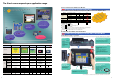
Using Video Inputs
The NS-CA002 has joined the NS-CA001 Video Input Unit.
Console
Console
RGB
Camera
Camera
You may want to input moving images
from a video camera or the image
output from a Vision Sensor, arrange
them on the PT screen, and capture
(save) the images or display the capture
data on the PT.
Display PC Screens with the NS-CA002
NS-CA002 RGB/Video Input Unit
(Supported by the NS12-V /NS10-V /NS8-V .)
An analog RGB input terminal is provided in addition to two
video input interface terminals. A single video or analog
RGB display is possible on the NS-series PT. In that case,
video display is possible in user-defined positions and sizes.
Touch switches and parts, such as lamps, can be
overlapped on the video display. The display of parts will
not disappear.
NS-CA001 Video Input Unit
(Supported by the NS12-V /NS10-V /NS8-V .)
Four video input interfaces are provided, so four video or
CCD cameras can be connected. Up to four images can be
displayed simultaneously if the image size is 320x240
pixels.
Image capture data read function
BMP data captured and saved in a Memory Card can be
read on the PT. BMP data displayed in thumbnails
can be selected and displayed on the captured data display
screen that will appear for the command button.
If an error occurs, the image when the error occurred can be displayed
on the NS screen. This is useful for on-site error analysis.
Note: Two video signals cannot be simultaneously input to a
single screen.
Saving Displayed Video Images to a Memory
Card in BMP Format
Image Capture Function
When necessary, the displayed image can be captured and
saved in a Memory Card in BMP format. The saved image
can then be uploaded from remote personal computer via
Ethernet or Serial connection.
The number of images that can be saved depends on the
capacity of Memory Card. As an example, about 50 images
from a 640x480 display (about 600 Kbytes each) can be
saved in a 30-Mbyte Memory Card.
PT System
Ver. 6 or Higher
For Operators
For Experts
Display machine
status simply.
Display PLC memory
areas without using tools.
Display program
without using tools
Display machine
status simply.
Do not want to be aware of
ladder programs and PLC
memory areas.
Only want to display I/O
comments and I/O status.
Display PLC memory
areas without using tools.
Want to display and change the
PLC memory areas without
showing the PLC program.
Display program
without using tools
Want to identify the fault location
by checking the actual PLC
program.
Want to change part of the
program, a timer/counter, without
connecting tools.
The NS monitors machine status for who and how machines
are managed to help speed recover from problems.
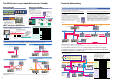
Monitoring and Setting PLC Data
Ladder Monitor Function
(NS12-V /NS10-V /NS8-V )
The Ladder Monitor Software provided with the
CX-Designer can be used to monitor states,
search for addresses and instructions, and
monitor multiple I/O points at the same time in
CS/CJ-series PLCs ladder programs via a serial,
Controller Link, or Ethernet connection. Copy
the Ladder Monitor software to a Memory Card
and install the Memory Card in the NS-series PT
to enable these monitoring and searching
operations. It is also possible to display I/O
comments created with the CX-Programmer
using an I/O Comment Extract Tool.
Monitoring Execution of
the PLC's Ladder Program
Switch Box Function
The Switch Box Function has been added to the
NS-series Programmable Terminals. The Switch
Box Function can be used to monitor the status
of each bit in a word or a combination of user-
selected bits organized like a ladder program
section. The Switch Box Function makes it
possible to perform basic troubleshooting on
the factory floor even without a computer.
Easily Displaying the Status of
Particular Bits in Ladder Programs
when Errors Occur
Device Monitor Function
The Device Monitor Function is a standard feature
in the NS-series Programmable Terminals. Data in
the PLC’s I/O memory can be accessed directly
(read and written.) The Device Monitor provides
functions that can significantly reduce the time
needed to set up the system, such as displaying a
block of consecutive PLC data area addresses and
inputting/verifying parameters in CPU Bus Units
and Special I/O Units.
Monitoring PLC I/O Data for
the Purpose of Device Debugging
and Maintenance
Solve with the Ladder Monitor
function
Solve with the Switch Box
function
Solve with the Device Monitor
function
Facilitate Equipment Maintenance
Smart Active Parts
The following Smart Active Parts are provided and can be installed on the NS-Designer (version 6 or higher).
For CS/CJ AND CS1D CPU Unit
Error Log Monitor, Online Battery Change Button, etc.
For Serial Communications Boards/Units
Communications Status Displays (Error Monitor), Ports Settings, etc.
For Ethernet Units/CLK Units
Network Status Displays (Error Monitor and Network Node Status), etc.
For MC/MCH Unit
JOG Running, Search Zero Position, Program Running, Error Displays,
I/O Status Monitor, PV Monitor, etc.
For NC/NCF Unit
JOG Running, Direct Running, Memory Running (NC Only), Error
Displays I/O Status Monitor, PV Monitor, etc.
Wireless Terminals for WT30
Monitoring Slave Operating Status in a Wireless Environment
For Servo (R88D-WT, R7D-AP) (See note.)
PV Monitor, Parameter Settings, Error Displays, Driver Information
Displays, I/O Status Monitor, etc.
For Inverters (See note.)
Rotation Speed/Monitoring Output Frequency, Other Parameter
Settings, etc.
For DeviceNet
DRT2 Maintenance/Status Information, IN/OUT Information, etc.
For Temperature Controllers (E5 R, E5ZN, E5 N and
CJ1W-TC)
Run Monitor, PID Settings SP Settings, Alarm Settings, Input
Correction Settings, etc.
For Sensors (E3X-DRT)
Threshold Settings, Monitoring Light Reception Levels, Etc.
For the SmartSlice GRT1 Series
Communications Unit Status, Warning/Alarm Flags, Network
Joining/Leaving Status
Integrating Special Unit Functions or Component Peripheral Tool Functions into PTs
Note: Smart Active Parts require a Serial Communications Units/Boards
(version 1.2 or later).
From CX-Designer version 1.0, the Ladder Monitor software is
stored in the following folder on the CD-ROM. Copy it to a Memory
Card (sold separately) to use it.
CX-One Disk 3: \Utility\CX-Designer\English\
LadderMonitorFunc.
CX-Designer CD-ROM: \Utility\English\LadderMonitorFunc.