
Datasheet


64
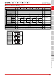
G3VM-@A@/@D@/@B@/@E@ MOS FET Relays
DIP
SOP
SSOP
USOP
VSON
S-VSON
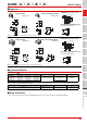
Introduction
General-purpose High-load-voltage Multi-contact-pair
(2a, 2b, and 1a1b)
High-current and
Low-ON-resistance
Small and High-
dielectric-strength
High-dielectric-
strength
Current-limiting
Low-output-capacitance
and Low-ON-resistance
Small and High-
load-voltage
Certified Models with
Standards Certification
G3VM-
@
A
@
/
@
D
@
/
@
B
@
/
@
E
@
■Electrical Characteristics (Ta = 25°C)
■Recommended Operating Conditions
For usage with high reliability, Recommended Operation Conditions is a measure that takes into account the derating of Absolute
Maximum Ratings and Electrical Characteristics.
Each item on this list is an independent condition, so it is not simultaneously satisfy several conditions.
Item Symbol
G3VM-61A1
G3VM-61D1
G3VM-61B1
G3VM-61E1
G3VM-351A
G3VM-351D
G3VM-351B
G3VM-351E
G3VM-353A
G3VM-353D
G3VM-353B
G3VM-353E
G3VM-401A
G3VM-401D
G3VM-401B
G3VM-401E
Unit
Measurement
conditions
Input
LED forward
voltage
V
F
Minimum 1.0
V I
F=10 mATypical 1.15
Maximum 1.3
Reverse
current
I
R Maximum 10 μAVR=5 V
Capacitance
between
terminals
C
T Typical 30 pF V=0, f=1 MHz
Trigger LED
forward
current
I
FT
(IFC)
*2
Typical 1.6 1
mA
G3VM-353A/353D/
353B/353E :
I
OFF=10 μA
Others :
I
O
=Continuous load
current ratings
Maximum 3
Release
LED forward
current
IFC
(IFT)
*2
Minimum 0.1 mA
G3VM-353A/353D/
353B/353E :
IO=150 mA
Others :
I
OFF=100 μA
Output
Maximum
resistance
with output
ON
R
ON
Typical
Connection A
1
35
(25)
15 18 17
Ω
G3VM-61A1/61D1/61B1/
61E1/351A/351D/351B/
351E/401A/401D/401B/
401E :
IF=5 mA,
I
O
=Continuous load
current ratings
Values in parentheses
are for t < 1 s.
G3VM-353A/353D/
353B/353E :
I
O
=Continuous load
current ratings
Connection B
−
0.5
−
28
−
8
−
11
Connection C
0.25 14 4 6
Maximum
Connection A
2
50
(35)
25 35
Connection B
− 1
−
40
−
14
−
20
Connection C
− 20 7 10
Current
leakage
when the
relay is open
I
LEAK Maximum 1 μA
G3VM-353A/353D/
353B/353E :
I
F=5mA,
V
OFF
=Load voltage ratings
Others :
V
OFF
=Load voltage ratings
Capacitance
between
terminals
C
OFF Typical 130 30 85 40 pF V=0, f=1 MHz
Capacitance
between I/O
terminals
C
I-O Typical 0.8 pF f=1 MHz, VS=0 V
Insulation
resistance
between I/O
terminals
R
I-O
Minimum 1000
MΩ
V
I-O=500 VDC,
R
OH≤60%
Typical 10
8
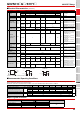
Turn-ON time tON
Typical 0.8 0.3 0.1 − 0.3
ms
I
F
=5 mA, R
L
=200
Ω
,
VDD=10 V *1
Maximum 2 1
Turn-OFF time tOFF
Typical 0.1 1 − 0.1
Maximum 0.5 1 3 1
*1. Turn-ON and Turn-OFF Times *2. These values are for Relays with NC contacts
Item Symbol
G3VM-61A1
G3VM-61D1
G3VM-61B1
G3VM-61E1
G3VM-351A
G3VM-351D
G3VM-351B
G3VM-351E
G3VM-353A
G3VM-353D
G3VM-353B
G3VM-353E
G3VM-401A
G3VM-401D
G3VM-401B
G3VM-401E
Unit
Load voltage
(AC peak/DC)
V
DD Maximum 48 280 320 V
Operating LED
forward current
I
F
Minimum 5
mA
Typical 7.5 10 − 7.5
Maximum 25
Continuous load
current (AC peak/DC)
IO Maximum 500 100 150 100 120
Ambient operating
temperature
Ta
Minimum -20
°C
Maximum 65
V
OUT
I
F
t
ON
t
OFF
10%
90%
I
F
1
2
4(6)
3(4)
R
L
V
DD
V
OUT