
Controller Link Units Operation Manual


17
Specifications and Configurations Section 1-2
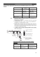
Note A Controller Link Support Board can be installed into an IBM PC/AT or com-
patible computer to connect the computer to the network. Refer to the Con-
troller Link Support Boards Operation Manual (W307) for details.
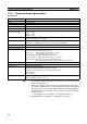
Item Specifications
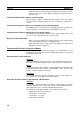
Model CVM1-CLK21 CQM1H-CLK21
External
appearance
Installation
devices
None required. None required.
PLC CVM1 and CV-series PLCs CQM1H-CPU51/61
Max No. of
Units per PLC
4 maximum 1 maximum
Installation site Install onto a CPU Backplane or
Expansion CPU Backplane (Classi-
fied as a CPU Bus Unit.)
Connected as a Communi-
cations Unit between Power
Supply Unit and CPU Unit.
Storage loca-
tion for net-
work
parameters
CPU Bus Unit Area (in the CPU Unit
parameter area)
Controller Link Unit
Storage loca-
tion for routing
tables
CPU Unit parameter area DM 6450 to DM 6499 in
CPU Unit
Weight 550 g 200 g
Current con-
sumption
300 mA 290 mA
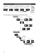
CPU Backplane
Expansion CPU
Backplane
3/5/10 slots
11 slots
CPU
Unit
Of these
14, 16, or
21 slots,
installa
tion is
possible
in up to 4
slots.
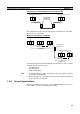
CPU
Unit
Power Supply
Unit
Connect
here.