
Controller Link Units Operation Manual


361
Memory Areas Appendix B
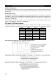
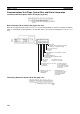
Parameters for Automatically Setting Data Links: DM 2000 + 100 × (Unit No.) + 1 to + 9 (See
page 147.)
CQM1H-series PLCs
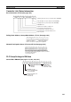
AR Area
Data Link Start Bit: AR 07 (See page 113.)
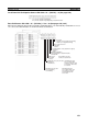
Number of send words per node of area 1 (BCD)
Rightmost 4 digits of data link start word of area 2 (BCD)
Leftmost digit of data link start word
of area 2 (BCD)
First data link status word (BCD)
15 8 7 0
15 14 13 12 11 10 9 8 7 6 5 4 3 2 1 0
16151413121110987654321
+1
+2
+3
+4
+5
+6
+8
32 31 30 29 28 27 26 25 24 23 22 21 20 19 18 17
+9
+7
Area 2 type
Number of send words per node of area 2 (BCD)
Area 1 data link start word (BCD)
Area 1 type
BCD: Set the value as binary-coded decimal.
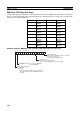
Nodes to participate in the data links
The numbers indicate node numbers.
The value assigned indicates whether the
node is to participate in the data links.
Participate: 1
Not
p
artici
p
ate: 0
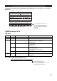
Word Bits Name Contents
AR 00 11 Communications Unit Error Flag Turns ON when an error occurs in a Communications Unit.
AR 01 11 Communications Unit Restart Bit Turn ON this bit to restart the Communications Unit.
AR 02 00 to 07 Response code Contains the completion code for network instructions
(SEND(90), RECV(98), or CMND(
––)).
(See page 191.)
08 Network Instruction Error Flag
0: Normal end to SEND(90), RECV(98), or CMND(
––).
1: Abnormal end
(See page 190.)
09 Network Instruction Enable Flag
0: SEND(90), RECV(98), or CMND(
––) execution not possi-
ble (already executing)
1: Execution possible (not executing)
(See page 190.)
15 Communications Unit Connected
Flag
Turns ON when a Communications Unit is mounted to the
PLC.
AR 03 00 to 15 Communications Unit Servicing
Time
Indicates the servicing time for the last cycle in 0.1-ms units
(4-digit BCD.)
Data link Start Bit (AR0700)
Start: Changed from OFF to ON or set to ON
when power is turned on
Stop: Changed from ON to OFF
15 14 13 12 11 10 9 8 765 4 3 210