
Controller Link Units Operation Manual


119
Setting Data Links Section 5-2
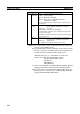
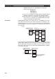
CVM1 and CV-series PLCs
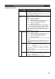
Setting item Setting range
PLC model Set the model of the PLC’s CPU Unit.
Nodes 1 to 32
Set the address of the refresh nodes.
It cannot be set to a parameter exceeding the “maximum node
address” of the network parameter.
First data link sta-
tus word
Set the first word to store data link status. An area of 16 words is
used.
CIO Area: CIO 0001 to CIO 2540 (*1)
LR Area: LR 000 to LR 184 (*2)
DM Area: DM 0000 to DM 8176 (CV500/CVM1-CPU01-EV@)
DM 0000 to DM 24560 (Other CPU Units)
EM Area: Banks 00 to 07, EM 0000 to EM 32750
(EM must be installed)
*1: When CIO 000 is specified or when the default setting (
– – –
– –
) is left unchanged, the default first status word will be
used. Refer to 5-4 Checking Data Link Status for details.
*2: When a word between LR 000 and LR 184 is specified, the
data link area will be allocated between CIO 1000 and
CIO 1184.
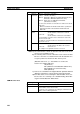
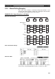
Area 1 Data link
start word
CIO Area: CIO 0000 to CIO 2555
LR Area: LR 000 to LR 199 (*)
DM Area: DM 0000 to DM 8191 (CV500/CVM1-CPU01-EV@)
DM 0000 to DM 24575 (Other CPU Units)
EM Area: Banks 00 to 07, EM 0000 to EM 32765
(EM must be installed)
The same area cannot be set for both area 1 and area 2. Set dif-
ferent areas.
*: When a word between LR 000 and LR 199 is specified, the
data link area will be allocated between CIO 1000 and
CIO 1199.
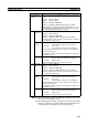
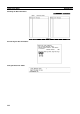
Number of
words
Remote nodes: 0 to the number of source words
Set the number of words to be received.
Local node: 0 to 1,000
Set the number of words to be transmitted.
The total number of words in area 1 and area 2 in each node
must not exceed 1,000.
The numbers of words in both area 1 and area 2 in each node
must not be set to 0.
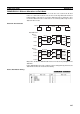
Offset
Remote nodes:
0 to one less than number of source words
Set the offset for the data to be received.
Local node: Cannot be set.
This setting is not required if an offset is not used.