Cat. No.
CS1W-ETN21 (100Base-TX) CJ1W-ETN21 (100Base-TX) Ethernet Units Construction of Networks Operation Manual Revised January 2006
iv
Notice: OMRON products are manufactured for use according to proper procedures by a qualified operator and only for the purposes described in this manual. The following conventions are used to indicate and classify precautions in this manual. Always heed the information provided with them. Failure to heed precautions can result in injury to people or damage to property. !DANGER Indicates an imminently hazardous situation which, if not avoided, will result in death or serious injury.
Unit Versions of CS/CJ-series Unit Versions A “unit version” has been introduced to manage Units in the CS/CJ Series according to differences in functionality accompanying Unit upgrades. Notation of Unit Versions on Products The unit version is given to the right of the lot number on the nameplate of the products for which unit versions are being managed, as shown below. Product nameplate CS1WUNIT Unit version Example for unit version 1.3 Lot No. Lot No.
Using Unit Version Label The following unit version label is provided with the Ethernet Unit. This label can be attached to the front of the Ethernet Unit to differentiate between Ethernet Units with different unit versions. Unit Version Notation Product nameplate In this manual, the unit version of a Ethernet Unit is given as shown in the following table. Notation used in this manual Ver. 2.0 or later number shown to right of the lot number Ethernet Unit Ver. 1.
viii
TABLE OF CONTENTS PRECAUTIONS . . . . . . . . . . . . . . . . . . . . . . . . . . . . . . . . . . . . . xxi 1 Intended Audience . . . . . . . . . . . . . . . . . . . . . . . . . . . . . . . . . . . . . . . . . . . . . . . . . . . . . . . . . . . xxii 2 General Precautions . . . . . . . . . . . . . . . . . . . . . . . . . . . . . . . . . . . . . . . . . . . . . . . . . . . . . . . . . . xxii 3 Safety Precautions. . . . . . . . . . . . . . . . . . . . . . . . . . . . . . . . . . . . . . . . . . . . .
TABLE OF CONTENTS SECTION 4 Ethernet Unit Memory Allocations. . . . . . . . . . . . . . . . . . . . . . 77 4-1 CIO Area Allocations . . . . . . . . . . . . . . . . . . . . . . . . . . . . . . . . . . . . . . . . . . . . . . . . . . . . . . . . . 78 4-2 DM Area Allocations . . . . . . . . . . . . . . . . . . . . . . . . . . . . . . . . . . . . . . . . . . . . . . . . . . . . . . . . . 86 4-3 Auxiliary Area Data . . . . . . . . . . . . . . . . . . . . . . . . . . . . . . . . . . . . . . . . . . . . .
TABLE OF CONTENTS Appendices A Ethernet Network Parameters . . . . . . . . . . . . . . . . . . . . . . . . . . . . . . . . . . . . . . . . . . . . . . . . . . 231 B Buffer Configuration . . . . . . . . . . . . . . . . . . . . . . . . . . . . . . . . . . . . . . . . . . . . . . . . . . . . . . . . . 233 C TCP Status Transitions . . . . . . . . . . . . . . . . . . . . . . . . . . . . . . . . . . . . . . . . . . . . . . . . . . . . . . . . 235 D ASCII Characters . . . . . . . . . . . . . . . . . . .
TABLE OF CONTENTS xii
About this Manual: This manual describes the installation and operation of the CS1W-ETN21 and CJ1W-ETN21 Ethernet Units (100Base-TX) and includes the sections described below. Please read this manual carefully and be sure you understand the information provided before attempting to install or operate the Ethernet Unit. Be sure to read the precautions provided in the following section. Section 1 introduces the features, describes the system configuration and Unit parts, and provides Unit specifications.
Relevant Manuals The following table lists CS and CJ-series manuals that contain information relevant to Ethernet Units. Manual number Model Name Contents W420 CS1W-ETN21 CJ1W-ETN21 W421 CS1W-ETN21 CJ1W-ETN21 W343 CS1W-ETN01 CS1W-ETN11 CJ1W-ETN11 Ethernet Units Oper- Describes the installation and operation of the 10Base-5 ation Manual and 10Base-T Ethernet Units.
Manual number W446 Model Name Contents WS02-CXPC1-EV6 CX-Programmer Ver. 6.1 Operation Manual W444 CXONE-AL@@C-E W445 CXONE-AL@@C-E W341 CQM1H-PRO01-E CQM1-PRO01-E C200H-PRO27-E W336 CS1W-SCB21-V1/41-V1 CS1W-SCU21-V1 CJ1W-SCU21-V1/41-V1 CX-One Setup Man- Describes operating procedures for the CX-One FA Inteual grated Tool Package. Refer to this manual for operating procedures for the CXOne FA Integrated Tool Package.
xvi
Read and Understand this Manual Please read and understand this manual before using the product. Please consult your OMRON representative if you have any questions or comments. Warranty and Limitations of Liability WARRANTY OMRON's exclusive warranty is that the products are free from defects in materials and workmanship for a period of one year (or other period if specified) from date of sale by OMRON.
Application Considerations SUITABILITY FOR USE OMRON shall not be responsible for conformity with any standards, codes, or regulations that apply to the combination of products in the customer's application or use of the products. At the customer's request, OMRON will provide applicable third party certification documents identifying ratings and limitations of use that apply to the products.
Disclaimers CHANGE IN SPECIFICATIONS Product specifications and accessories may be changed at any time based on improvements and other reasons. It is our practice to change model numbers when published ratings or features are changed, or when significant construction changes are made. However, some specifications of the products may be changed without any notice. When in doubt, special model numbers may be assigned to fix or establish key specifications for your application on your request.
xx
PRECAUTIONS This section provides general precautions for using the CS1W-ETN21 and CJ1W-ETN21 Ethernet Units (100Base-TX). The information contained in this section is important for the safe and reliable application of Ethernet Units. You must read this section and understand the information contained before attempting to set up or operate an Ethernet Unit. 1 2 3 4 5 6 Intended Audience . . . . . . . . . . . . . . . . . . . . . . . . . . . . . . . . . . . . . . . . . . . . . General Precautions . . . . . .
1 Intended Audience 1 Intended Audience This manual is intended for the following personnel, who must also have knowledge of electrical systems (an electrical engineer or the equivalent). • Personnel in charge of installing FA systems. • Personnel in charge of designing FA systems. • Personnel in charge of managing FA systems and facilities. 2 General Precautions The user must operate the product according to the performance specifications described in the operation manuals.
Operating Environment Precautions 4 • Emergency stop circuits, interlock circuits, limit circuits, and similar safety measures must be provided in external control circuits. !Caution Tighten the screws on the terminal block of the AC Power Supply Unit to the torque specified in the operation manual. The loose screws may result in burning or malfunction. 4 Operating Environment Precautions !Caution Do not operate the control system in the following locations: • Locations subject to direct sunlight.
5 Application Precautions • Always turn OFF the power supply to the CPU Unit, Slaves, and Communications Units before attempting any of the following. Not turning OFF the power supply may result in malfunction or electric shock. • Mounting or dismounting I/O Units, CPU Units, Memory Packs, or Master Units. • Assembling the Units. • Setting DIP switches or rotary switches. • Connecting cables or wiring the system.
6 Conformance to EC Directives • Check the user program for proper execution before actually running it on the Unit. Not checking the program may result in unexpected operation. • Observe the following precautions when wiring the communications cable. • Separate the communications cables from the power lines or high-tension lines. • Do not bend the communications cables past their natural bending radius. • Do not pull on the communications cables.
Conformance to EC Directives 6 Low Voltage Directive Always ensure that devices operating at voltages of 50 to 1,000 V AC and 75 to 1,500 V DC meet the required safety standards for the PLC (EN61131-2).
SECTION 1 Features and System Configuration This section introduces the features, describes the system configuration and Unit parts, and provides Unit specifications. 1-1 1-2 1-3 1-4 1-5 1-6 Ethernet Unit Function Guide . . . . . . . . . . . . . . . . . . . . . . . . . . . . . . . . . . . . . 2 1-1-1 Overall System Configuration Example . . . . . . . . . . . . . . . . . . . . . . 2 1-1-2 Determining the Objectives . . . . . . . . . . . . . . . . . . . . . . . . . . . . . . . 2 Features . . . .
Section 1-1 Ethernet Unit Function Guide 1-1 Ethernet Unit Function Guide 1-1-1 Overall System Configuration Example The following diagram shows an example of an overall system configuration using Ethernet Units.
Ethernet Unit Function Guide Section 1-1 Connecting through Multiple Segments Use the TCP/IP version of the FINS communications service (i.e., FINS/TCP). FINS/TCP is a new function supported by these Ethernet Units (CS1WETN21 and CJ1W-ETN21). It provides automatic recovery at the TCP/IP layer from communications errors (such as packet loss) that occur during multilevel routing. For CX-Programmer (version 4.0 or higher), FINS/TCP can be used to directly connect to the PLC online.
Section 1-1 Ethernet Unit Function Guide Connecting through multiple segments, such as over the Internet: Use FINS/TCP. CX-Programmer FINS Internet IP router Intranet Firewall (Server room) Connecting from a computer with a dynamic private IP address: Use FINS/TCP or FINS/UDP. (Office floor) CX-Programmer FINS Ethernet Ethernet Router Router (Production line) Connecting within the same segment: Use FINS/UDP.
Section 1-1 Ethernet Unit Function Guide Intranet Production line A Ethernet Unit Ethernet Router FINS message communications Connecting through multiple segments: Use FINS/TCP. Router Production line B Mail communications Ethernet Unit Ethernet Unit PLC PLC FINS message communications Memory Card Connecting within the same segment: Use FINS/UDP.
Section 1-1 Ethernet Unit Function Guide Mail software Receiving e-mail E-mail Internet IP router Intranet Firewall (Server room) (Office floor) DNS server POP3 server SMTP server SNTP server Ethernet Mail software Receiving e-mail Router Ethernet Router (Production line) Ethernet Ethernet Unit Sending e-mail (5) Monitoring PLC changes and sending equipment status to the operator by e-mail Reference PLC's I/O memory data sent as attached file SECTION 2 Mail Send Function in the Operation Manu
Section 1-1 Ethernet Unit Function Guide Mail software Sending e-mail Internet IP router Intranet Firewall (Server room) (Office floor) DNS server POP3 server SMTP server SNTP server Ethernet Mail software Sending e-mail Router Ethernet Router (Production line) Writing command File attachment enabled Ethernet Ethernet Unit Writing command File attachment enabled Receiving e-mail Receiving e-mail at the PLC Reference SECTION 3 Mail Receive Function in the Operation Manual Construction of Applic
Section 1-2 Features Automatically Adjusting the PLC's Internal Clock at Regular Intervals Operation Use the automatic clock adjustment function. With the automatic clock adjustment function, the SNTP server's clock is taken as the standard for automatically adjusting the built-in clock of the PLC connected to the Ethernet Unit. The adjustment can be regularly executed at a specified time (once a day) and it can be executed each time by the ladder program.
Section 1-2 Features Improved FINS Message Communications The following functions have been improved over previous Ethernet Unit models. They allow the scale of the system to be increased, and can give greater flexibility to the system configuration including the host computer. • Expanded number of nodes (to 254 max., from 126 max.) • Communications are now enabled even if the host computer's IP address is dynamic. (DHCP client computers can be handled, including TCP/IP and UDP/IP.
Section 1-2 Features • In addition to using the existing Mail Send Switch, or having e-mail sent at regular intervals, it is possible to set triggers for sending e-mail (for example, by having e-mail sent when a PV in the CPU Unit's I/O memory reaches a certain value (size comparison), or when the bit at a specified address turns ON). • Up to eight of these e-mail send conditions (destination, trigger type, etc.
Section 1-3 System Configuration 1-3 1-3-1 System Configuration System Configuration CX-Programmer CX-Integrator FinsGateway (3) Hub (2) Twisted-pair cable 100 m max. (1) CS1W-ETN21 Ethernet Unit (100Base-TX) CS-series PLC 1-3-2 (1) CJ1W-ETN21 Ethernet Unit (100Base-TX) CJ-series PLC Devices Required for Constructing a Network The basic configuration for a 100Base-TX Ethernet System consists of one hub to which nodes are attached in star form using twisted-pair cable.
Section 1-3 System Configuration Personal computer running Windows CX-Programmer Unit Setup Ethernet Unit CPU Bus Unit System Setup Area CS/CJ-series CPU Unit Making Settings in the Routing Table Area (with CX-Integrator) OMRON Communications Units use OMRON's original FINS network system. Make the settings for the FINS network and the relay path, as required, in the Routing Table Area allocated to the non-volatile memory in the CPU Unit. Use CX-Integrator to make the settings.
Section 1-4 Specifications Personal computer running Windows User-created software CX-Programmer FinsGateway Windows Ethernet Unit CS/CJ-series CPU Unit 1-4 1-4-1 Specifications General Specifications CS-series Ethernet Unit Item Specifications Model number CS1W-ETN21 Type Applicable PLCs 100Base-TX (Can be used as 10Base-T) CS-series PLCs Unit classification Mounting location CS-series CPU Bus Unit CPU Rack or Expansion Rack Number of Units that can be mounted 4 max.
Section 1-4 Specifications Item Ambient operating temperature 0 to 55°C Specifications Ambient humidity Atmosphere 10% to 90% (with no condensation) Must be free of corrosive gas. Ambient storage temperature Weight −20 to 75°C 200 g max.
Section 1-4 Specifications 1-4-2 Dimensions CS1W-ETN21 ETN21 100M ERH TCP FTP HOST RUN ERC SD RD LNK UNIT NO. 0 1 ×161 ×160 130 NODE NO.
Section 1-4 Specifications CJ1W-ETN21 65 2.7 31 ETN21 ERC SD RD LNK 100M ERH TCP FTP HOST RUN EF012 6789 345 ABCD EF012 6789 345 UNIT No. NODE No. x161 ABCD EF012 6789 345 ABCD 90 x160 2.7 100BASE-TX 10BASE-T (Unit: mm) 1-4-3 Software Configuration The software supported by the Ethernet Unit runs in the layers shown in the following diagram. The components that form the various layers are defined below the diagram.
Section 1-5 Overview of Communications Functions 5. UDP (User Datagram Protocol) Performs data communications. Data resends, priority control, flow control, and other measures to ensure communications reliability are not performed for UDP communications, so the transmitted data may not arrive at the destination node. To increase reliability, it is necessary to program special measures into the user applications. 6.
Section 1-5 Overview of Communications Functions Executing, from the host computer, FINS commands with UDP/IP or TCP/IP headers enables various control operations, such as the reading and writing of I/O memory between PLCs, mode changes, and file memory operations. For example, it is possible to connect online via Ethernet from FINS communications applications such as the CX-Programmer, and to perform remote programming and monitoring. (See note.) Note Use CX-Programmer version 4.0 to use TCP/IP.
Section 1-5 Overview of Communications Functions A total of eight ports (UDP and TCP combined) can be used for socket services. UNIX computer, etc.
Section 1-5 Overview of Communications Functions 1-5-3 FTP Server Function The Ethernet Unit has a built-in FTP server, so other computers on the Ethernet can read or write individual files on a Memory Card mounted to the CPU Unit or in EM File Memory. This allows files to be exchanged between the host computer and the PLC, with the host computer functioning as an FTP client and the PLC as an FTP server.
Section 1-5 Overview of Communications Functions (2) An SMTP server is required to use the mail send function. (3) Mail server settings require specialized knowledge, so they should always be handled by the network administrator. (4) Be sure that you have a clear understanding of the mail system before using this function. (5) Mail my not always be delivered. Depending on factors such as the condition of the network, mail that has been sent may not arrive at its destination.
Section 1-5 Overview of Communications Functions 1-5-6 Automatic Clock Adjustment Function The Ethernet Unit can acquire clock information from the SNTP server at a particular time or when a dedicated bit turns ON, and it can refresh the internal clock information of the CPU Unit to which it is mounted. SNTP server Ethernet Clock information Ethernet Unit CS/CJ-series CPU Unit Note (1) An SNTP server is required to use this function.
Section 1-6 Nomenclature and Functions 1-6 Nomenclature and Functions This section describes Ethernet Unit component names, settings, and LED indicators. 1-6-1 Component Names CS-series Ethernet Units CS1W-ETN21 (100Base-TX) Front ETN21 100M ERH TCP FTP HOST RUN ERC SD RD LNK UNIT NO. NODE NO. 0 0 1 ×161 Indicators Display the operating status of the Unit. ×160 Unit Number Switch Used to set the Ethernet Unit's unit number in one digit hexadecimal.
Section 1-6 Nomenclature and Functions Note The Ethernet address can also be checked using the FINS command, CONTROLLER DATA READ. For details, refer to 7-3-2 CONTROLLER DATA READ on page 160. CJ-series Ethernet Units CJ1W-ETN21 (100Base-TX) Front Slider For mounting to other Units. ETN21 Indicators Display the operating status of the Unit. RUN ERC SD RD LNK 100M ERH TCP FTP HOST EF012 6789 345 ABCD ABC EF012 6789 345 UNIT No. NODE No.
Section 1-6 Nomenclature and Functions Example ETN21 RUN ERC SD RD LNK IP ADDRESS 100M ERH TCP FTP HOST EF012 6789 345 ABCD EF012 6789 345 133.113. UNIT No. SUBNET MASK 255.255.255.0 NODE No. ×161 Attach the label to the front of the Ethernet Unit between the node number switches and the Ethernet connector. ABCD EF012 6789 345 ×160 ABCD IP ADDRESS 133.113. 0. 42 0. 42 SUBNET MASK 255.255.255.
Section 1-6 Nomenclature and Functions Indicator Color Green Status Not lit 100M (Transfer speed) Green Lit Not lit Normal operation 10 Mbps (10Base-T) ERC (Ethernet Unit error) Red Lit Not lit 100 Mbps (100Base-TX) Unit normal Lit Node address not between 1 and 254 A hardware (e.g., internal memory) error has occurred. ERH (CPU Unit error) Red Not lit Lit CPU Unit normal An error has occurred at the CPU Unit.
Section 1-7 Comparison with Previous Models 1-7 Comparison with Previous Models Item Previous models CS1W-ETN11 CJ1W-ETN11 10Base-T CS1W-ETN21 CJ1W-ETN21 100Base-TX, 10Base-T Number of nodes PLC maintenance via the Internet 126 Not possible to send FINS commands from a personal computer to the PLC via the Internet. 254 Can send commands (including FINS commands) by e-mail over the Internet from a personal computer to the PLC (using the mail receive function).
Section 1-8 Unit Version Upgrade Information 1-8 Unit Version Upgrade Information The details of the upgrade to the Ethernet Unit version are as follows: ■ Unit Version 1.3 Upgrade ■ The unit settings and status monitoring for the Ethernet Unit can be easily performed from a Web browser. Function prohibiting access using FINS/ UDP from nodes with dynamically changed IP addresses Access to change the remote IP address from a node using FINS/UDP can be prohibited (IP address protection).
SECTION 2 Installation and Initial Setup This section explains how to install the Ethernet Unit and make the initial settings required for operation. 2-1 2-2 2-3 2-4 2-5 Overview of Startup Procedure . . . . . . . . . . . . . . . . . . . . . . . . . . . . . . . . . . . . 30 Switch Settings . . . . . . . . . . . . . . . . . . . . . . . . . . . . . . . . . . . . . . . . . . . . . . . . 31 2-2-1 CS-series Ethernet Units. . . . . . . . . . . . . . . . . . . . . . . . . . . . . . . . . .
Section 2-1 Overview of Startup Procedure 2-1 Overview of Startup Procedure The following procedure is the same for the CS Series and CJ Series. Determine the local IP address and address conversion method. Refer to SECTION 5 Determining IP Addresses. Set the unit number. Refer to 2-2 Switch Settings. Set the node number. Refer to 2-2 Switch Settings. Mount the Unit to the PLC. Refer to 2-3 Mounting to a PLC. Connect to the network using twisted-pair cable. Refer to 2-4 Network Installation.
Section 2-2 Switch Settings 2-2 2-2-1 Switch Settings CS-series Ethernet Units Setting the Unit Number The unit number is used to identify individual CPU Bus Units when more than one CPU Bus Unit is mounted to the same PLC. Use a small screwdriver to make the setting, taking care not to damage the rotary switch. The unit number is factory-set to 0. Setting range: 0 to F Note (1) Turn OFF the power supply before setting the unit number.
Section 2-2 Switch Settings 2-2-2 CJ-series Ethernet Units Setting the Unit Number The unit number is used to identify individual CPU Bus Units when more than one CPU Bus Unit is mounted to the same PLC. Use a small screwdriver to make the setting, taking care not to damage the rotary switch. The unit number is factory-set to 0. EF01 6789 2345 ABCD Note UNIT No. Setting range: 0 to F (1) Turn OFF the power supply before setting the unit number.
Mounting to a PLC Section 2-3 Unit Operating Mode Change Function If the node address is set to 00, the Unit operating mode change function will start. This function changes the format for the Unit Setup (in the CPU Bus Unit System Setup Area) when converting to a CS1W-ETN21 or CJ1W-ETN21 Ethernet Unit from one of the previous models (CS1W-ETN01/11 or CJ1W-ET11). For details, refer to 2-12 Converting from Previous Models.
Section 2-4 Network Installation CPU Rack 10 Units max. End cover P C I S P C U Expansion Backplane 10 Units max. End cover P I S I Up to four Ethernet Units can be mounted. Expansion Backplane 10 Units max. End cover P I S I Expansion Backplane 10 Units max. End cover P I S I PS: Power Supply Unit CPU: CPU Unit IC: I/O Control Unit II: I/O Interface Unit The CJ1W-ETN21 Ethernet Unit’s maximum current consumption is 370 mA.
Section 2-4 Network Installation 2-4-2 Recommended Products The following products are recommended for use with the CS1W-ETN21 Ethernet Unit.
Section 2-4 Network Installation • Do not lay the twisted-pair cable near devices that generate noise. • Do not lay the twisted-pair cable in locations subject to high temperatures or high humidity. • Do not lay the twisted-pair cable in locations subject to excessive dirt and dust or to oil mist or other contaminants. Hub Installation Environment Precautions • Do not install the hub near devices that generate noise. • Do not install the hub in locations subject to high temperatures or high humidity.
Section 2-4 Network Installation 2-4-4 Using Contact Outputs (Common to All Units) Communications errors can occur when Contact Output Units are mounted to the same Rack or connected to the same PLC as an Ethernet Unit due to noise generated by the contact outputs. Use one or more of the following measures when installing Contact Output Units and Ethernet Units on the same Rack. Mounting Location Mount (or connect) any Contact Output Units as far away from the Ethernet Unit as possible.
Section 2-5 Connecting to the Network 2-5 2-5-1 Connecting to the Network Ethernet Connectors The following standards and specifications apply to the connectors for the Ethernet twisted-pair cable. • Electrical specifications: Conforming to IEEE802.3 standards. • Connector structure: 2-5-2 RJ45 8-pin Modular Connector (conforming to ISO 8877) Connector pin Signal name 1 Transmission data + Abbr.
Section 2-6 Creating I/O Tables 1,2,3... 1. Lay the twisted-pair cable. 2. Connect the cable to the hub. Be sure to press in the cable until it locks into place. Request cable installation from a qualified professional. 3. Connect the cable to the connector on the Ethernet Unit. Be sure to press in the cable until it locks into place.
Section 2-6 Creating I/O Tables Programming Console Model number C200H-PRO27-E Key Sheet (required) CS1W-KS001-E CQM1-PRO01-E Recommended cable (required) CS1W-CN224 (cable length: 2.0 m) CS1W-CN624 (cable length: 6.0 m) CS1W-CN114 (cable length: 0.1 m) CX-Programmer (Version 3.20 or Higher) and CX-Integrator The operations are explained here using a Programming Console. For details regarding the CX-Programmer and the CX-Integrator, refer to the CX-Programmer User’s Manual.
Section 2-7 Unit Setup Procedure 2-7 Unit Setup Procedure Use the CX-Programmer (Ver. 3.20 or higher) for the Ethernet Unit Setup, and follow the procedure described below. Some functions added with unit version 1.3 require CX-Programmer version 5.0 or higher for setting. 1,2,3... 1. Connect the CX-Programmer online. The CX-Programmer can be connected to the PLC in either of the following ways: a. Connect the personal computer to the PLC by serial cable, through either a peripheral port or RS-232C port.
Unit Setup Procedure Section 2-7 3. Read the I/O tables from the PLC and select the Rack to which the Ethernet Unit is mounted. 4. Move the cursor to the Ethernet Unit and right-click. Select Unit Setup from the popup menu to display the window for making the Ethernet Unit Setup. The default settings are shown below. At the point where the Ethernet Unit is mounted and the I/O tables has just been created, the default values are in effect for all of the settings.
Using the Web Browser Setting Function Section 2-8 5. Make the required settings (i.e., the IP address in this case). 6. Transfer the settings to the PLC. Click on Yes in the following dialog box. 7. In order for the Ethernet Unit Setup to go into effect, the Unit must be restarted. Click on Yes in the following dialog box. 8. Check the Ethernet Unit's LED indicators. After the RUN indicator has turned OFF and then turned ON again, the Ethernet will recognize the new settings (i.e.
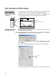
Using the Web Browser Setting Function 1,2,3... Section 2-8 1. Connect to the Ethernet Unit from the Web browser. In this example, the URL is specified as http://192.168.250.1/0 using the Ethernet Unit’s default IP address. 2. Select Settings from the menu on the left side of the window to display the Settings Menu.
Using the Web Browser Setting Function Section 2-8 3. Select 1. IP address and Protocols - System to display the Login Password field on the right of the window. 4. Input the default password (“ETHERNET” all in upper case) and click the Login Button. 5. The settings in the System menu will be displayed. The following window shows the default system settings. 6. Make the required settings (i.e., the IP address in this example).
Section 2-9 Basic Settings 7. After entering the correct values, click the Set Button followed by the Regist Button to register them. The Set Button is used to transfer the entered values from the personal computer, and temporarily register them in the Ethernet Unit. The Regist Button stores the set values that have been temporarily registered in the Ethernet to the flash memory (non-volatile memory) of the CPU Unit.
Section 2-9 Basic Settings Default Setting The Ethernet Unit operates using the default IP address when the Unit is mounted to the PLC and initially registered in the I/O tables (i.e., when the Unit settings have not been made and the IP Address Display/Setting in the CPU Bus Unit Words Allocated in the DM Area is still all zeros). The default IP address is determined as follows: Default IP address = 192.168.250.
Section 2-9 Basic Settings Example: Using the CX-Programmer to Set the IP Address to 10.3.65.1 When an IP address is set in the Unit Setup, that value is displayed in the IP Address Display/Setting Area in the DM Area words allocated for CPU Bus Units. When the IP address is set by the CX-Programmer, and the defaults are used for all other Unit settings, the settings will be as shown below. Item Status IP address Subnet mask Set by CX-Programmer. Uses value corresponding to IP address class.
Section 2-9 Basic Settings ■ Baud Rate Set the baud rate. Setting Auto (Default) 10Base-T Contents Automatically detects the baud rate between hubs. Operates with 100Base-TX (full duplex) whenever possible. Operates with 10Base-T (half duplex). ■ TCP/IP Keep-alive Setting Set the Liveness-Checking Interval. (This setting is enabled only when FINS/ TCP or TCP/IP socket services are used.
Section 2-10 Unit Setup for Particular Applications The default IP router is selected when no Network ID exists in the IP router table for the destination network number. To set the default IP router, set 0.0.0.0 for the IP address and set the default IP router's IP address for the router address. 2-10 Unit Setup for Particular Applications Aside from the basic settings, the required settings vary depending on the particular communications applications that are used.
Section 2-10 Unit Setup for Particular Applications CX-Programmer tab Settings SMTP Server specification type IP Address Host name Port No. Local mail address Mail Address Use POP before SMTP Mail address 1 Send Mail Mail address 2 Transmission trigger setting Trigger classification Interval time Mail address Transmission data classification For details, refer to SECTION 2 Mail Send Function in the Operation Manual Construction of Applications.
Section 2-11 Communications Test For details, refer to SECTION 5 Automatic Clock Adjustment Function in the Operation Manual Construction of Applications. Web Functions CX-Programmer tab HTTP Setting item Use Web function Password Port No. For details, refer to Appendix G Ethernet Unit Web Function.
Converting from Previous Models Section 2-12 2-11-3 Host Computer The PING command can be executed from the host computer to send an echo request packet to an Ethernet Unit. The method for using the PING command from a UNIX computer is given next. Method Input the following at the host computer prompt ($): $ ping IP_address(host_name) The destination is specified by its IP address or host name. If the host name is used, the host name must be defined in file /etc/hosts.
Section 2-12 Converting from Previous Models If the format change is from ETN11 mode to ETN21 mode, then there will be no effect on previous applications. If the change is from ETN21 mode to ETN11 mode, however, then certain limitations will go into effect. The following table shows the limitations that apply when operating in ETN11 mode.
Converting from Previous Models Section 2-12 Checking the CPU Bus Unit System Setup Area Format Checking with the CX-Programmer's Software Switches - Status Tab Window Checking with the CX-Programmer's Unit Setup Window ■ Window Display in ETN21 Mode 55
Section 2-12 Converting from Previous Models ■ Window Display in ETN11 Mode ■ Checking by Reading Words Allocated in the CIO Area 15 14 13 12 11 10 9 8 7 6 5 4 3 2 1 0 n+17 System Setting Format Bit address Changing the CPU Bus Unit System Setup Area Format 11 10 9 0 0 0 8 0 0 0 Other 1 0 Format classification ETN11 mode ETN21 mode Reserved The CPU Bus Unit System Setup Area format can be changed in either of the following two ways.
Converting from Previous Models Section 2-12 ■ Using the CX-Programmer's Unit Setup 1. Select Change Ethernet Unit Mode from the Options Menu in the Unit Setup. 2. The following confirmation message will be displayed. To change the mode, click Yes. 3. After the mode has been changed, the following confirmation message will be displayed. Click OK to restart the Ethernet Unit. After the Unit has been restarted, it will begin to operate in ETN21 mode.
Section 2-12 Converting from Previous Models ■ Manipulating the Rotary Switches for the Node Address with a Precision Screwdriver Converting from ETN11 Mode to ETN21 Mode 1. Turn OFF the power to the PLC, and set the Ethernet Unit's rotary switches for the node address as follows: Node address ×16 1 0 ×6 0 0 RUN Indicators ERC ERH Not lit Not lit Not lit 2. Turn ON the power to the PLC.
Section 2-12 Converting from Previous Models 7. Turn OFF the power to the PLC and return the Ethernet Unit's rotary switches for the node address to its original setting. 8. Turn ON the power to the PLC. Node address ×161 - ×16 - 0 Indicators RUN ERC ERH Lit Not lit Not lit Converting from ETN21 Mode to ETN11 Mode 1.
Section 2-12 Converting from Previous Models Note If an error occurs in the mode change, remove the Ethernet Unit, create the I/O tables, and correct the settings using the procedures described in this section. 7. Turn OFF the power to the PLC and return the Ethernet Unit's rotary switches for the node address to its original setting. 8. Turn ON the power to the PLC.
SECTION 3 CX-Programmer Unit Setup This section describes how to install the Ethernet Unit and make the initial settings required for operation. 3-1 Setup . . . . . . . . . . . . . . . . . . . . . . . . . . . . . . . . . . . . . . . . . . . . . . . . . . . . . . . . 62 3-2 FINS/TCP . . . . . . . . . . . . . . . . . . . . . . . . . . . . . . . . . . . . . . . . . . . . . . . . . . . . 64 3-3 DNS. . . . . . . . . . . . . . . . . . . . . . . . . . . . . . . . . . . . . . . . . . . . . . . . . . . . . .
Section 3-1 Setup 3-1 Setup Item Contents Set the method for specifying IP addresses for broadcasting in FINS/ UDP. • All 1 (4.3BSD): Broadcast with host number set to all ones. • All 0 (4.2BSD): Broadcast with host number set to all zeros. Normally the default setting should be used. Default All 1 (4.3BSD) IP Address Set the local IP address for the Ethernet Unit. Sub-net Mask Set the subnet mask for the Ethernet Unit.
Section 3-1 Setup Item Destination IP Address (Change Dynamically) Contents Select to dynamically change the remote (destination) IP address for FINS/UDP. To prohibit dynamic changes, deselect this box. Baud Rate Select the Ethernet baud rate for the Ethernet Unit. Select either automatic detection or 10Base-T. (For 100Base-TX, select automatic detection.) Set the liveness-checking interval.
Section 3-2 FINS/TCP 3-2 FINS/TCP FINS/TCP Connection Setup Item No. Use IP address to protect 64 Contents Default Shows the connection number. This is a network API used when TCP is used for the FINS communications service. It corresponds to a socket in the socket services. Up to 16 can be used at a time, and they are identified by connection numbers 1 to 16. The Ethernet Unit can thus simultaneously execute the FINS communications service by TCP with up to 16 remote nodes.
Section 3-2 FINS/TCP The following settings can be made for each connection number. Item Contents Default FINS/TCP Mode For each connection number, this setting specifies Server the Ethernet Unit for use as either a server or a client. • When the Ethernet Unit is used as a server: The Ethernet Unit opens a connection with that connection number and waits for service requests (FINS commands) from clients.
Section 3-3 DNS 3-3 DNS DNS Server Setup 66 Item IP Address Contents Default Set the IP address for the DNS server. None The DNS server is required when specifying the POP3, SMTP, or SNTP servers by host name for the mail send function or mail receive function. Port No. Set the port to be used for connecting to the DNS server. This setting does not normally need to be changed. 0 (Number 53 is used.) Retry timer Set the time to elapse before retrying when a connection to the DNS server fails.
Section 3-4 SMTP 3-4 SMTP SMTP Server Setup Item Server specification type IP Address Contents Default Select whether the SMTP server used for send- IP Address ing mail is to be specified by IP address or the host's domain name (i.e., host name). Set the IP address for the SMTP server used for 0.0.0.0 sending mail. This setting is enabled only when “IP address” is selected as the method for specifying the server. Host name Set the host domain name (i.e.
Section 3-5 POP 3-5 POP POP Server Setup Item Server specification type IP Address Contents Default Select whether the POP3 server used for receiving IP Address mail is to be specified by IP address or the host's domain name (i.e., host name). Set the IP address for the POP3 server used for receiving mail. This setting is enabled only when “IP address” is selected as the method for specifying the server. Host name Set the host domain name (i.e.
Section 3-6 Mail Address 3-6 Mail Address Destination Mail Address Setup Item Contents Default Mail Address 1 Set one of the addresses to which the Ethernet Unit None is to send mail. (Up to two address can be set.) Note: Mail can be sent to multiple addresses by punctuating the mail address with commas. Mail Address 2 Set one of the addresses to which the Ethernet Unit None is to send mail. (Up to two address can be set.
Section 3-7 Send Mail 3-7 Send Mail Item Trigger No. Send mail upon trigger 70 Contents Default Select a number as the trigger condition for send- --ing mail. Up to eight trigger numbers can be registered. Sets whether or not the selected mail trigger is to Not checked be enabled.
Section 3-7 Send Mail Item Mail Softtrigger ware type switch (Select only one.) Word value change Contents Default If this option is selected, mail is sent whenever the Checked Mail Send Switch turns ON. The Mail Send Switch is bit 03 of word n in the words allocated for CPU Bus Units.
Section 3-8 Receive Mail Item Interval time When “Periodic timer” is set as the mail trigger type When “Bit value change” or “Word value change” is set as the mail trigger type Contents Default Set the time interval for sending 0 mail. (10 minutes) 1 to 1,440 (10 to 14,400 min), in units of 10 min Set the time interval for monitor- 0 ing the value at a specified (1 second) address.
Section 3-8 Receive Mail Receive Attached File Setting Item Receive file with specified extension only Contents Default If this option is selected, only file attachments Not with specified extensions is accepted with mail. checked Use the checkboxes below to select which file extensions are to be accepted. Multiple extensions can be selected.
Section 3-9 Auto Adjust Time For details, refer to SECTION 3 Mail Receive Function in the Operation Manual Construction of Applications. 3-9 Auto Adjust Time SNTP Server Setup Item Contents Get the time information from the SNTP server If this option is selected, the CPU Unit's clock is set to the time at the SNTP server's clock. The clock can be changed only for the CPU Unit to which the Ethernet Unit is mounted. Set the time at which the SNTP server is to be accessed to synchronize the clocks.
Section 3-10 HTTP Item Retry timer Adjust Time Contents Default Set the time to elapse before retrying when a connec- 0 tion to the SNTP server fails. This setting does not (10 s) normally need to be changed. This sets in the CPU Unit's clock data the time differ- +0:0 ence made up from the SNTP server's clock data. To use the clock data from the SNTP server just as it is, input 0. For details, refer to SECTION 5 Automatic Clock Adjustment Function in the Operation Manual Construction of Applications.
HTTP 76 Section 3-10
SECTION 4 Ethernet Unit Memory Allocations This section describes the words allocated in the CIO Area and the DM Area for Ethernet Units. 4-1 CIO Area Allocations . . . . . . . . . . . . . . . . . . . . . . . . . . . . . . . . . . . . . . . . . . . 78 4-2 DM Area Allocations . . . . . . . . . . . . . . . . . . . . . . . . . . . . . . . . . . . . . . . . . . . 86 4-3 Auxiliary Area Data . . . . . . . . . . . . . . . . . . . . . . . . . . . . . . . . . . . . . . . . . . . .
Section 4-1 CIO Area Allocations 4-1 CIO Area Allocations The various kinds of data are stored in the offset positions shown in the following diagram, from the beginning word in the area for each Unit. The beginning word n is calculated by the following equation: Beginning word n = CIO 1500 + (25 × unit number) Offset Bit 15 8 7 0 Data direction Related communications services Unit Control Switch CPU Unit to Ethernet Unit Socket Services n+1 UDP Socket No.
Section 4-1 CIO Area Allocations Unit Control Bits (CPU Unit to Ethernet Unit) 15 14 13 12 11 10 9 8 7 6 5 4 3 2 1 0 n Socket Force-close Switch Mail Send Switch Automatic Clock Adjustment Switch Bit 0 to 1 (Not used.) --- Manipulated by ----- 2 Socket Force-close Switch ON User All sockets are forcibly closed when this bit turns ON. OFF Unit ON User OFF Unit ON User Turned OFF by Unit after sockets are closed. User mail is sent when this bit turns ON.
Section 4-1 CIO Area Allocations Status of UDP/TCP Sockets 1 to 8 (Ethernet Unit to CPU Unit) 15 14 13 12 11 10 9 8 7 6 5 4 3 2 1 0 n+1 to n+16 Data Received Flag Opening Flag Results Storage Error Flag Receiving Flag TCP/UDP Open Flag Sending Flag Closing Flag Bit 0 1 2 3 Flag Status Opening Flag Receiving Flag Sending Flag Closing Flag OFF Unit ON Unit ON during receive processing. (Turns ON when receive request is received.
Section 4-1 CIO Area Allocations Receiving Flag (Bit 1) Turns ON when a receive request is received either by control bit manipulation or the CMND(490) instruction, and turns OFF again when the receive processing has been completed. When CMND(490) is used, the Results Storage Error Flag (bit 14) will turn ON at the same time as the Receiving Flag turns OFF if there is an error in the Results Storage Area designation.
Section 4-1 CIO Area Allocations Service Status (Ethernet Unit to CPU Unit) 15 14 13 12 11 10 9 8 7 6 5 4 3 2 1 0 n+17 FTP Status System Setup Format Accessing Memory, Sending Mail Link Status Accessing Memory, Receiving Mail Bit 0 Name FTP Status Flag Status ON OFF 1 Accessing Memory, ON Sending Mail OFF 2 Accessing Memory, ON Receiving Mail Manipulated Unit operation by Unit FTP server operating. (FTP client connected.) Unit FTP server on standby. (FTP client not connect.
Section 4-1 CIO Area Allocations Accessing Memory (Receiving Mail) (Bit 2) This bit turns ON while CPU Unit memory is being accessed to store an attached file using the mail receive function, and it turns OFF after the file has been stored. System Setup Format (Bits 8 to 11) These bits show the format classification in the CPU Bus Unit System Setup Area.
Section 4-1 CIO Area Allocations Bit 11 Error SNTP server error 12 SMTP server error OFF ON Unit Unit OFF when SNTP server operation is normal. ON when the following errors occur during SMTP server operation: • An illegal server IP address or host name is set. • A timeout occurs during communications with the server. • The verification time from the server has expired (when POP before SMTP is set). 13 POP server error OFF ON Unit Unit OFF Unit OFF when SMTP server operation is normal.
Section 4-1 CIO Area Allocations Bit 8 0 9 1 10 2 11 3 12 13 14 15 4 5 6 7 Switch Status Manipulated Unit operation by UDP Open Request ON User UDP socket opened when switch is turned Switch ON. OFF Unit Unit turns OFF switch when open processing has been completed (i.e., when a connection has been made). User Passive TCP socket opened when switch is TCP Passive Open ON Request Switch turned ON. OFF Unit Unit turns OFF switch when open processing has been completed (i.e.
Section 4-2 DM Area Allocations These bits show the status of FINS/TCP connections. Bit 0 Switch Status FINS/TCP Connection No.1 ON OFF 1 FINS/TCP Connection No.2 to 14 to FINS/TCP Connection No.15 15 FINS/TCP Connection No.16 4-2 ON Manipulated Unit operation by Unit Turned ON by the Unit when a connection is established. Unit Turned OFF by the Unit when the connection is terminated. Unit Turned ON by the Unit when a connection is established.
Section 4-2 DM Area Allocations The meanings of the items shown in the above diagram are explained on the following pages. For details regarding the related communications services shown in the diagram, refer to the indicated sections.
Section 4-2 DM Area Allocations TCP Socket No. (1 to 8): Number of Bytes Received (Ethernet Unit to CPU Unit) 15 14 13 12 11 10 m+1 to m+8 9 8 7 6 5 4 3 2 1 0 Number of Bytes Received (0000 to 07C0 hex) For each TCP socket, the number of bytes of data in the reception buffer is stored in one word.
Section 4-2 DM Area Allocations IP Address Display/Setting Area m+98 15 14 13 12 11 10 9 (1) (2) m+99 (5) 8 7 (6) 6 5 (3) 4 3 2 (7) 1 (4) 0 (8) IP address: (1)(2).(3)(4).(5)(6).(7)(8) (Hex) If the local IP address in the CPU Bus Unit System Setup is set to a value other than 0.0.0.
Section 4-3 Auxiliary Area Data 4-3 Auxiliary Area Data The following table and descriptions cover the words and bits in the Auxiliary Area of PLC memory that are related to the Ethernet Unit. Read-only Bits/Words Word(s) Bit(s) A202 A20200 to A20207 Name Communications Port Enabled Flags Function Bits A20200 to A20207 turn ON when a network instruction (SEND, RECV, CMND, or PMCR) can be executed with the corresponding port number. Bits 00 to 07 correspond to communications ports 0 to 7.
Section 4-3 Auxiliary Area Data Word(s) Bit(s) A417 A41700 to A41715 Name Function Settings CPU Bus Unit Error, When an error occurs in a data exchange between 0: No error Unit Number Flags the CPU Unit and a CPU Bus Unit, the CPU Bus 1: Error Unit Error Flag (A40207) and the corresponding flag in A417 are turned ON. Bits 00 to 15 correspond to unit numbers 0 to F. The ERR/ALM indicator on the front of the CPU Unit will flash, but CPU operation will continue.
Auxiliary Area Data 92 Section 4-3
SECTION 5 Determining IP Addresses This section explains how to manage and use IP addresses. 5-1 5-2 5-3 IP Addresses . . . . . . . . . . . . . . . . . . . . . . . . . . . . . . . . . . . . . . . . . . . . . . . . . . 94 5-1-1 IP Address Configuration . . . . . . . . . . . . . . . . . . . . . . . . . . . . . . . . . 94 5-1-2 Allocating IP Addresses . . . . . . . . . . . . . . . . . . . . . . . . . . . . . . . . . . 94 5-1-3 Ethernet Unit IP Address Settings . . . . . . . . . . . . . . . . . . .
Section 5-1 IP Addresses 5-1 IP Addresses Ethernet networks use IP addresses for communications. IP addresses identify both the Ethernet network and the node (host computer, Ethernet Unit, etc.). IP addresses must be set and controlled so that they are not duplicated. 5-1-1 IP Address Configuration IP addresses are made up of 32 bits of binary data divided into four 8-bit fields called octets. These four octets provide the network number (net ID) and host number (host ID).
Section 5-1 IP Addresses 5-1-3 Ethernet Unit IP Address Settings An IP address must be set even for the Ethernet Unit before Ethernet communications can proceed. Either use the default for the Ethernet Unit's IP address, or else use a Peripheral Device to set it in the DM Area words allocated to the Unit as a CPU Bus Unit or in the CPU Bus Unit System Setup. For details, refer to 2-7 Unit Setup Procedure.
Section 5-2 IP Addresses in FINS Communications 5-2 5-2-1 IP Addresses in FINS Communications Specifying Nodes in FINS Communications Services With FINS communications services on an Ethernet network, IP addresses, UDP port numbers, and TCP port numbers are paired with FINS node addresses to specify nodes on the network. Application level FINS Transport level UDP Internet level IP Node number TCP UDP port number TCP port number Must be allocated.
Section 5-2 IP Addresses in FINS Communications Pairing IP Addresses with FINS Node Addresses at Local Nodes A particular IP address is allocated to each communications node, including Ethernet Units. The IP address must be paired with the FINS node address (1 to 254) by one of the following methods. Automatic Generation Method (Dynamic/Static) Set the relation between the IP address and the FINS node address for the Ethernet Unit according to the following equation.
Section 5-2 IP Addresses in FINS Communications 5-2-2 Pairing Addresses in Internal Tables FINS/UDP Communications Methods Automatic Generation (Dynamic) When the Ethernet Unit is turned ON or restarted, the following values are set for addresses in the internal table.
Section 5-2 IP Addresses in FINS Communications IP Address Table Method With this method, FINS node addresses are converted to IP addresses based on a correspondence table (IP address table) that is preset in the Unit setup. The IP address table is set using the CX-Programmer in IP Address Table under Settings in the Unit Setup. It can be registered for nodes in different segments and with different network numbers.
Section 5-2 IP Addresses in FINS Communications • Connection method: FINS/UDP • FINS Node Address Not Registered to IP Address Table The following address is registered to the internal table. • Remote IP address: Local IP address network number + FINS node address • Remote UDP port number: UDP port number set for local Unit • Connection method: FINS/UDP With the combined method, records of FINS nodes registered to the IP address table are not dynamically changed.
IP Addresses in FINS Communications Using the ETN11compatible Mode Section 5-2 For Ethernet Unit with unit version 1.4 or later, operating specifications can be made compatible with the CS1W-ETN11/CJ1W-ETN11 for all methods (automatic generation (dynamic), I/O address table, or combined). (Dynamic changes, however, are prohibited for the destination IP address in ETN11compatible mode.
IP Addresses in FINS Communications Section 5-2 FINS/TCP Communications Method Pairing in the FINS/TCP Method Note Internal Processing With the FINS/TCP method, communications are first established for each connection, and then remote FINS node addresses are mutually converted. (See note.) Then FINS message communications are executed. In this way, remote FINS node addresses and remote IP addresses are paired for each connection.
Section 5-2 IP Addresses in FINS Communications Personal computer or Ethernet Unit (client) Ethernet Unit (server) (1) The connection is established. Local FINS node number A (2) The local device (such as a personal computer) sends notification that its FINS node number is A.
Section 5-2 IP Addresses in FINS Communications 5-2-3 Application Examples Responding to Computers with Changed IP Addresses FINS/UDP Communications Method With FINS/UDP, whether using the automatic conversion method (dynamic), the IP address table method, or the combined method, remote FINS node addresses and remote IP addresses in the internal table are changed after FINS messages are received.
Section 5-2 IP Addresses in FINS Communications applications, such as mail servers, are normally allocated fixed IP addresses. Ethernet Units in PLC systems are also allocated fixed IP addresses.
Section 5-2 IP Addresses in FINS Communications Models Supporting Automatic Generation Method (Static) Product Model/Series/ Version CS-series Ethernet Unit 100BASE-TX CS1W-ETN21 10BASE-5 10BASE-T CS1W-ETN01 CS1W-ETN11 CJ-series Ethernet Unit 100BASE-TX CJ1W-ETN21 10BASE-T 10BASE-5 CJ1W-ETN11 CV500-ETN01 CV/CVM1-series Ethernet Unit FinsGateway Supports automatic generation method (static)? Yes Yes: Simply called “automatic generation method.
Section 5-3 Private and Global Addresses Product 5-2-5 Programmable Terminal Model/Series/ Version NS Series Open Network Controller (ONC) --- Supports combined method? No: Set manually. FINS communications are not possible with personal computers set automatically by DHCP. Pairing IP Addresses and FINS Node Addresses The following table shows the methods for pairing IP address and FINS node addresses, and the relation between fixed and variable address, for both FINS/UDP and FINS/TCP.
Section 5-3 Private and Global Addresses Intranet Personal computer, CX-Programmer, etc. Ethernet Firewall PLC Private address IP router Private address Internet Not output to Internet Global address (required) Not output to Internet Intranet Global address IP router Private address Private address Personal computer, CX-Programmer, etc.
Section 5-3 Private and Global Addresses 5-3-2 Using a Private Address for the Ethernet Unit Intranet CX-Programmer, etc. FINS/TCP client computer FINS communications FTP Socket Ethernet Communications in intranet Firewall PLC IP router Sending mail Receiving mail Ethernet Unit: Private address Internet E-mail can be sent and received through the Internet. Intranet FINS communications FTP Socket IP router CX-Programmer, etc.
Section 5-3 Private and Global Addresses • With FINS/UDP, when the IP address (private address) of a computer serving as a DHCP client is changed, the Ethernet Unit's IP address conversion method will be the automatic generation method (dynamic), the combined method, or the IP address table method. When FINS/TCP is used, IP addresses can be changed automatically. 2. Transferring Files • Files can be transferred, using FTP protocol, between the PLC and a device such as a personal computer (i.e.
Section 5-3 Private and Global Addresses 5-3-3 Ethernet Unit with a Global Address Intranet CX-Programmer, etc. FINS/TCP client computer Ethernet Communications over Internet Firewall Private address IP router Internet Not output to Internet Global address (required) Not output to Internet Intranet Global address IP router Private address Private address Firewall Ethernet Communications in intranet PLC Ethernet Unit: Global address Conditions for Using Communications Applications 1,2,3...
Section 5-3 Private and Global Addresses 3. Sending Mail • The PLC can send the Ethernet Unit's IP address to the SMTP server by mail via the intranet, even if it as a private address. • The TCP port number (default: 25) to be used for SMTP cannot be used if prohibited by a firewall in the communications path. Also, with some communications companies, there may be restrictions, based on mail security considerations, on using POP before SMTP. 4.
SECTION 6 FINS Communications This section provides information on communicating on Ethernet Systems and interconnected networks using FINS commands. The information provided in the section deals only with FINS communications in reference to Ethernet Units. FINS commands issued from a PLC are sent via the SEND(090), RECV(098), and CMND(490) instructions programmed into the user ladder-diagram program.
Section 6-1 Overview of FINS Communications 6-1 6-1-1 Overview of FINS Communications Communications On an Ethernet Network Data is sent and received as UDP/IP packets or TCP/IP packets on an Ethernet network. PLC or host computer Ethernet Unit Packet (FINS command) Ethernet Packet (FINS response) Ethernet Unit PLC In the FINS communications service, both an IP address for IP (the Internet layer) and a FINS node address for FINS (the application layer) are used for the remote device.
Section 6-1 Overview of FINS Communications • When FINS nodes are connected on the same Ethernet segment: Use the FINS/UDP method between those nodes. Note FINS/UDP offers a slight advantage in performance. • When FINS nodes are connected over multiple IP network layers: Use the FINS/TCP method between those nodes. Note FINS/TCP offers superior communications quality. • When the quality of connections is unreliable, as with wireless LAN: Use the FINS/TCP method between those nodes.
Section 6-2 FINS/UDP Method 6-2 6-2-1 FINS/UDP Method Overview FINS/UDP Features The FINS/UDP method is a FINS communications method that uses the UDP/ IP protocol. UDP/IP is a connectionless communications protocol. When a message is sent from one node to another, the two nodes have an equal relationship and there is no clear connection. If using TCP is like making a telephone call, then UDP is more like delivering a memo by hand.
Section 6-2 FINS/UDP Method UDP Port Numbers for FINS/UDP The UDP port number is the number for UDP to identify the application layer (i.e., the FINS communications service in this case). When communications are executed by UDP/IP, this port number must be allocated to the communications service. The default setting for the FINS/UDP local UDP port number (i.e., the Ethernet Unit's UDP port number) is 9600. To set another number, make the setting for the FINS/UDP port using the Setup Tab in the Unit Setup.
Section 6-3 FINS/TCP Method 6-3 6-3-1 FINS/TCP Method Overview FINS/TCP Features The FINS/TCP method is a FINS communications method that uses the TCP/ IP protocol. TCP/IP is a connection-type communications protocol. Before a message is sent from one node to another, it is necessary to establish a virtual circuit, i.e., a connection. Once a connection has been established, communications are quite reliable.
Section 6-3 FINS/TCP Method • Once a FINS/TCP connection (connection number, remote IP address) has been set in the Unit Setup, it can be dynamically changed from the ladder program using a FINS command (i.e., FINS/TCP CONNECTION REMOTE NODE CHANGE REQUEST). FINS/TCP Frame Format Ethernet Ver. 2 The following diagram shows the structure of a TCP packet sent over an Ethernet network.
Section 6-3 FINS/TCP Method FINS/TCP Connection Status (Word n+23) While a connection with a remote node is established, the bit corresponding to the FINS/TCP connection status turns ON in the section of the CPU Bus Unit words allocated in the CIO Area. The bit turns OFF if the connection is terminated by a communications error or a FINS command (i.e., FINS/TCP CONNECTION REMOTE NODE CHANGE REQUEST).
Section 6-3 FINS/TCP Method Even if the connection is closed at the FINS/TCP client, requests continue to be made to the FINS/TCP server every few seconds to open a connection. Note After the Ethernet Unit is powered up or restarted, the IP address for the connection used as the FINS/TCP client is the remote IP address set under the FINS/TCP Tab in the Unit Setup. To dynamically change the remote IP address (i.e.
Section 6-4 Creating Routing Tables 6-4 Creating Routing Tables When the FINS communications service is used, routing tables must be created in advance. Routing tables are required in the following circumstances. • When communicating with a PLC or computer on another network (e.g., remote programming or monitoring using FINS messages or a CX-Programmer) • When multiple Communications Units are mounted to a single PLC (i.e., CPU Unit).
Section 6-4 Creating Routing Tables The following example shows routing tables for sending data from PLC #1 (the local node: network address 1, node address 1) to PLC #4 (the destination node: network address 3, node address 2).
Section 6-4 Creating Routing Tables 6-4-3 Routing Table Setting Examples ■ Example 1: Local Network Table for a PLC With Multiple Units Mounted This example shows the local network table settings for a PLC to which multiple CPU Bus Units are mounted. Ethernet network Controller Link network (Network #A) (Network #B) PS: CPU: ETN: CLK: E C C P T L P S N K U Power Supply Unit CPU Unit Ethernet Unit Controller Link Unit Unit #a Unit #b Local Network Table No.
Section 6-4 Creating Routing Tables ■ Example 3: All Nodes This example uses the following configuration to show the routing tables for all nodes. Unit #5 Node #6 Unit #3 Node #4 Unit #2 Node #3 Network #20 C L K E T N CE L T PLC KN 2 PLC 4 Unit #0 Node #1 C L K CPU Bus Unit No. 05 CPU Bus Unit No. 03 02 PLC #3 Routing Table (Local network table) Local No. network 1 010 2 030 3 CPU Bus Unit No. 04 07 PLC #4 Routing Table (Local network table) Local No. network 1 020 2 3 CPU Bus Unit No.
Section 6-5 Using FINS Applications 6-5 Using FINS Applications 6-5-1 CX-Programmer (CX-Server) The following examples show how to connect online from a CX-Programmer on an Ethernet network to a PLC on the Ethernet network. ■ System Configuration Example 1: No Routing In this example, an online connection is made by FINS/UDP to a PLC on an Ethernet network (PLC1 in the diagram below) from a CX-Programmer/CXIntegrator connected to the Ethernet network.
Section 6-5 Using FINS Applications CX-Programmer's Unit Setup Setup Tab Item Setting Broadcast All ones (4.3BSD) FINS/UDP port IP address Default (9600) 0.0.0.0 (Use default IP address.) Subnet mask IP address conversion 0.0.0.
Section 6-5 Using FINS Applications Example: Network Settings (Network Tab) Note When FinsGateway is selected as the network type, make sure that the frame length is set to 2,000 bytes max.
Section 6-5 Using FINS Applications ■ System Configuration Example 2: Using Routing Tables In this example, an online connection is made via the Ethernet to a PLC on a Controller Link network (PLC 3 below) from a CX-Programmer/CX-Integrator connected to the Ethernet network. Conditions • FINS/UDP method • IP address conversion: Automatic generation method (dynamic) Controller Link Unit Node address: 1 IP address: 192.168.250.
Section 6-5 Using FINS Applications • Local Network Table Unit number Local network number 0 1 1 2 • Relay Network Table None Example: PLC 2 and PLC 3 Routing Table Settings • Local Network Table Unit number 0 Local network number 2 • Relay Network Table In order to relay from PLC2/3 to the final network number 1, it is necessary to relay via node address 1 (i.e., the Controller Link Unit) on relay network number 2. Final network number 1 Relay network number Relay node address 2 1 2.
Section 6-5 Using FINS Applications • Network Tab • Network number Set the network number for the personal computer (Ethernet port). • Local node address Set the personal computer (Ethernet port) node address (1 to 254) on the Ethernet network. Set the unit number in decimal (16 to 31) for the personal computer (Ethernet port). • Communication unit number • Communication Unit Tab • UDP port number Set the local UDP port number for the personal computer (Ethernet port). The default is 9600.
Using FINS Applications Section 6-5 • UDP Nodes Tab: Automatic Generation Method (Dynamic or Passive) • UDP Nodes Tab: IP Address Table Method or Combined Method Click the Add Button, and then set the IP address table in the following Ethernet Node Definition Dialog Box.
Section 6-5 Using FINS Applications • Node address: Set the remote FINS node address. • IP address: Set the remote IP address. • TCP Nodes Tab Click the Add Button, and then set the IP address table in the following Ethernet Node Definition Dialog Box.
Section 6-5 Using FINS Applications • Node address: • IP address: Set the remote FINS node address. Set the remote IP address. • Destination port number: Set the FINS/TCP port number for the remote node. Normally the PLC's default setting of 9600 should be specified. • Keep-alive setting: Sets the keep-alive function. Normally this should be selected. 3.
Section 6-6 Communicating between OMRON PLCs CX-Programmer's Unit Setup Setup Tab Item Broadcast Setting All ones (4.3BSD) FINS/TCP port IP address Default (9600) 0.0.0.0 (Use default IP address.) Subnet mask Baud rate 0.0.0.0 Automatic detection IP router tables None FINS/TCP Tab Not set. (All defaults are used.) FinsGateway ETN_UNIT Setup TCP Nodes Tab: Ethernet Node Definition Dialog Box Item 6-6 Setting Node address IP address 2 192.168.250.
Section 6-6 Communicating between OMRON PLCs Note Item Data contents Specifications The following data is sent and received with the execution of each instruction. SEND(090): Sends request for remote node to receive data, and receives response data. RECV(098): Sends request for remote node to send data, and receives response data. CMND(490): Sends any FINS command and receives response data. Communications port number Response monitor time Ports 0 to 7 (Eight transmissions can occur simultaneously.
Section 6-6 Communicating between OMRON PLCs 6-6-3 Using SEND(090), RECV(098), and CMND(490) Make the settings shown below when using the SEND(090), RECV(098), and CMND(490) instructions in the user’s ladder-diagram program in the PC. SEND(090) The SEND(090) instruction sends the data in n number of words, starting from the beginning word S at the local node, to the words starting from the beginning word D at the remote destination node (node address N).
Section 6-6 Communicating between OMRON PLCs RECV(098) With the RECV(098) instruction, the data in m number of words, starting from the beginning word S at the remote node (node address M) is received at the words starting from the beginning word D at the local node.
Section 6-6 Communicating between OMRON PLCs CMND(490) The CMND(490) instruction sends n bytes of command data, starting from the beginning word S at the local node, to the node at node address N. the data in m number of words, starting from the beginning word S at the remote node (node address M) is received at the words starting from the beginning word D at the local node.
Section 6-6 Communicating between OMRON PLCs Commands Addressed to CS/CJ-series CPU Units The following table provides a list of FINS commands that can be processed by a CS/CJ-series CPU Unit. For details, refer to the CS/CJ-series Programmable Controllers Communications Commands Reference Manual (W342). For details on FINS commands that can be processed by the Ethernet Unit, refer to SECTION 7 FINS Commands Addressed to Ethernet Units.
Section 6-6 Communicating between OMRON PLCs Usage File memory Debugging 6-6-4 Command code MR SR Name Function 22 22 01 02 FILE NAME READ SINGLE FILE READ Reads file memory data. Reads a specified length of file data from a specified position within a single file. 22 03 SINGLE FILE WRITE Writes a specified length of file data from a specified position within a single file. 22 22 04 05 FILE MEMORY FORMAT FILE DELETE 22 07 FILE COPY Formats (initializes) the file memory.
Section 6-6 Communicating between OMRON PLCs Communications Port Enabled Flag Execution condition C KEEP(011) A Input A remains ON from start to completion of communications instruction. Operand, control data created with @MOV and @XFER. Creates operand and control data in a given area. Reset B A Communications instructions @SEND @RECV @CMND Executes communications instructions. Communications Port Enabled Flag A DIFU(013) B Creates reset input.
Communicating between OMRON PLCs Communications Port Completion Codes Section 6-6 The status of a SEND(090), RECV(098), and CMND(490) instruction after execution is reflected as a communications port completion code, in one word (two bytes) of data as shown in the following table. (The value is 0000 during instruction execution.) The recorded status is saved until execution of the next instruction.
Section 6-6 Communicating between OMRON PLCs Example 1 0 Communications Port Enabled Flag Communications instruction: SEND(090), RECV(098), CMND(490) Instruction 1 being executed. Instruction 2 being executed. Instruction 3 being executed.
Section 6-6 Communicating between OMRON PLCs 6-6-5 Program Example Execution condition (See note.) 000000 A20207 120002 S KEEP 120000 R When the Communications Port Enabled Flag for port 7 is ON, and RECV(098) is not being executed, the send execution program will start when execution condition CIO 000000 turns ON. 120001 120000 @MOV(21) #000A D00000 Input CIO 120000 remains ON from the start of SEND(090) execution until completion.
Section 6-6 Communicating between OMRON PLCs (Continued from previous page.) Execution condition (See note.) 000001 A20207 120000 S KEEP 120002 When the Communications Port Enabled Flag for port 7 is ON, and SEND(090) is not being executed, the transmission execution program will start when execution condition CIO 000001 turns ON. R 120003 120002 @MOV(21) #0010 D00005 Input CIO 120002 remains ON from the start of RECV(098) execution until completion.
Section 6-6 Communicating between OMRON PLCs 6-6-6 Transmission Delays The methods of computing the maximum time required from execution of the SEND(090), RECV(098), and CMND(490) instructions until processing is completed are described in this section. SEND(090) The transmission delay for the SEND(090) instruction can be calculated using the following equation, which is illustrated in the following diagram. Max.
Section 6-6 Communicating between OMRON PLCs CPU Bus Unit Service Processing Time (Local Node) The processing time will be as follows, depending on the CPU processing mode settings at the CPU Unit: CPU execution mode Normal Mode Priority peripheral servicing Parallel processing with synchronous memory access Parallel processing with asynchronous memory access Processing time considerations Set time for peripheral servicing (Default: 4% of CPU Unit cycle time) 1 ms max.
Section 6-6 Communicating between OMRON PLCs CPU Bus Unit Service Processing Time (Remote Node) The processing time will be as follows, depending on the CPU processing mode settings at the CPU Unit. CPU processing mode settings Processing time considerations Normal Mode Set peripheral servicing time Default: 4% of CPU Unit cycle time Priority peripheral servicing Ethernet Unit is given priority. Ethernet Unit is not given priority.
Section 6-6 Communicating between OMRON PLCs RECV(098) The transmission delay for the RECV(098) instruction can be calculated using the equation illustrated in the following diagram.
Section 6-6 Communicating between OMRON PLCs CPU Bus Unit Service Processing Time (Local Node 1) The processing time will be as follows, depending on the CPU processing mode settings at the CPU Unit: CPU processing mode settings Normal Mode Processing time considerations Set peripheral servicing time (Default: 4% of CPU Unit cycle time) Priority peripheral servicing Parallel processing with syn- 1 ms max.
Section 6-6 Communicating between OMRON PLCs CPU Bus Unit service processing time (remote node) The processing time will be as follows, depending on the CPU processing mode settings at the CPU Unit. CPU processing mode settings Normal Mode Priority peripheral servicing Processing time considerations 4% of CPU Unit cycle time Ethernet Unit is given priority. Time slice peripheral servicing execution time Ethernet Unit is not given priority.
Section 6-7 Precautions on High Traffic in FINS Communications nodes, traffic through the Ethernet Unit (e.g., socket servicing, FTP server communications, etc.), and the system configuration. Example Calculations The following example shows calculations for receiving 256 words between two PLC nodes using RECV(098).
Precautions on High Traffic in FINS Communications Section 6-7 For example, suppose that approximately 20 ms are required to process a single FINS frame (i.e., 20 ms from the time that the command is received at the Ethernet Unit until a response is sent). If 100 or more FINS frames (commands) are received at once from multiple communicating nodes, it will take approximately 2 seconds to send a response to the last command.
SECTION 7 FINS Commands Addressed to Ethernet Units This section describes the FINS commands that can be sent to an Ethernet Unit and the responses that are returned by the Ethernet Unit. 7-1 7-2 7-3 Command Codes and Response Codes . . . . . . . . . . . . . . . . . . . . . . . . . . . . . . 156 7-1-1 Command Code List . . . . . . . . . . . . . . . . . . . . . . . . . . . . . . . . . . . . . 156 7-1-2 Response Code List . . . . . . . . . . . . . . . . . . . . . . . . . . . . . . . . . . . . .
Section 7-1 Command Codes and Response Codes 7-1 7-1-1 Command Codes and Response Codes Command Code List The command codes listed in the following table can be sent to an Ethernet Unit.
Section 7-2 Socket Applications The MRES codes are shown in the following table along with the results they indicate. Refer to 8-5 Troubleshooting with Response Codes for details on response codes including the SRES.
Section 7-2 Socket Applications Parameters 7-2-2 Specifies the parameters for the command code. Parameters depend on the command being executed; for details, refer to the following pages. PLC Memory Areas The memory areas of the PLC that can be specified for results storage when executing commands from the PC are listed in the table below. The Variable type is set in the first byte of the results storage area. The remaining three bytes contain the address for communications.
Section 7-3 Command/Response Reference 7-3 Command/Response Reference This section describes the FINS commands that can be sent to Ethernet Units and the responses to each command. The command, response, and (where applicable) the results storage blocks are given with the commands in graphic form as shown in the following diagram. If the data is fixed, it is included in the blocks. If the data is variable, it is described following the blocks.
Section 7-3 Command/Response Reference 7-3-2 CONTROLLER DATA READ Reads the following data from the Ethernet model, version, IP address, subnet mask, FINS UDP port number, mode settings, Ethernet address.
Section 7-3 Command/Response Reference FFINS/TCP Port Number Setting 0: Default (9600) 1: Unit Setup value Baud Rate setting 0: Automatic detection 1: 10Base-T SNTP Server Specification Method 0: IP address 1: Host name SMTP Server Specification Method 0: IP address 1: Host name POP Server Specification Method 0: IP address 1: Host name System Setup Format Bit address 14 13 15 0 0 0 0 0 0 Format classification 12 0 1 Other Ethernet Address (Response) ETN11 mode ETN21 mode Reserved The Ethernet addr
Section 7-3 Command/Response Reference Parameters Error Flags (Response) 15 14 13 12 Indicates the operating status and errors that occurred when the Ethernet Unit was started.
Section 7-3 Command/Response Reference Address Disagreement The address conversion method was set for automatic generation, but the node address and the last byte of the local IP address do not agree, or other host sections are 0. EEPROM Error An error occurred in the EEPROM memory in the Ethernet Unit. Total Number of Packets Received (Response) The total number of packets received by the Ethernet Unit is returned.
Section 7-3 Command/Response Reference Parameters Test Data (Command, Response) This command specifies the data to be sent to the specified nodes. Up to 1,998 bytes can be specified. The response sends back data identical to the data specified in the command. An abnormality is assumed if the data returned in the response differs from the test data sent. Precautions The test destination node is the destination node specified in the CMND(194) instruction operands.
Section 7-3 Command/Response Reference Command Block 08 03 1,460 bytes max. Command code Test data Parameters Test Data (Command) This command specifies the data to be sent to the specified nodes. Up to 1,460 bytes can be specified. Precautions No response is made to this command.
Section 7-3 Command/Response Reference Error Log Data (Response) The specified number of error log records from the beginning record number is returned sequentially. The total number of bytes in the error log is calculated as the number of records x 10 bytes/record. Each error log record thus comprises 10 bytes, configured as follows: 1st byte Error code 10th byte Detailed Minutes Second Day Hour Year Month information Error Code, Detailed Information Details of the error stored in the record.
Section 7-3 Command/Response Reference 7-3-9 UDP OPEN REQUEST Requests processing to open a socket. Command Block 27 01 Results storage area Command code Local UDP port number UDP socket number Socket option Response Block 27 01 Command code Response code Results Storage Format Results storage response code Parameters Socket Option (Command) The socket option specified as 1 byte. The setting is not valid for this command. Set to 0.
Section 7-3 Command/Response Reference Response code 1002 1100 Description Command too small 1101 UDP socket number is out of range. Local UDP port number is 0. The variable type for the results storage area is out of range. 1103 220F Non-zero bit address specified for the results storage area. Specified socket is already open or is being closed. 2211 High traffic at Unit; cannot execute service.
Section 7-3 Command/Response Reference Number of Reception Bytes (Command, Results Storage Area) The maximum number of bytes of data to be received is given in the command. The number of bytes of data received will be stored in the results storage area. Up to 1,984 bytes can be specified. Timeout Value (Command) The maximum control time between receiving the receive request and storing the result.
Section 7-3 Command/Response Reference Command Block 27 03 1984 bytes max. Command code Results storage area UDP socket number Destination IP address Destination Number of UDP bytes sent port number Send data Socket option Response Block 27 03 Command code Response code Response code Number of bytes sent Results Storage Format Parameters Socket Option (Command) The socket option specified as 1 byte. The setting is not valid for this command. Set to 0.
Section 7-3 Command/Response Reference Response code 1100 1101 Description UDP socket number or number of bytes sent is out of range. The destination IP address is 0. Local UDP port number is 0. The variable type for the results storage area is out of range. 1103 220F Non-zero bit address specified for the results storage area. Specified socket is currently sending. 2210 2211 The specified socket is not open. High traffic at Unit; cannot execute service.
Section 7-3 Command/Response Reference Results Storage Area (Command) The area in which the results of the command execution are stored. The first byte specifies the memory area and data type (variable type). The 2nd to 4th bytes specify the beginning address of the results storage area. Refer to page 158 for details about the variable types and addresses that can be specified.
Section 7-3 Command/Response Reference 7 0 Bits Keep-alive specification 0: Keep-alive disabled 1: Keep-alive enabled TCP Socket Number (Command) The TCP socket number to be opened specified as 1 byte between 1 and 8. Results Storage Area (Command) The area in which the results of the command execution are stored. The first byte specifies the memory area and data type (variable type). The 2nd to 4th bytes specify the beginning address of the results storage area.
Section 7-3 Command/Response Reference Response Codes Response code 0000 Normal 0105 0302 Local IP address setting error CPU Unit error; execution not possible. 1001 1002 Command too large Command too small 1100 TCP socket number is out of range. Local TCP port number is 0. The variable type for the results storage area is out of range. 1101 1103 220F Description Non-zero bit address specified for the results storage area.
Section 7-3 Command/Response Reference Response Block 27 11 Command code Response code Results Storage Format Response Local port number code Parameters Socket Option (Command) The socket option is specified in one byte. 7 0 Bits Keep-alive specification 0: Keep-alive disabled 1: Keep-alive enabled TCP Socket Number (Command) The TCP socket number to be opened specified as 1 byte between 1 and 8. Results Storage Area (Command) The area in which the results of the command execution are stored.
Section 7-3 Command/Response Reference Response Codes Response code 0000 Normal 0105 0302 Local IP address setting error CPU Unit error; execution not possible. 1001 1002 Command too large Command too small 1100 TCP socket number is out of range. Remote IP address or the remote TCP port number is 0. The variable type for the results storage area is out of range. 1101 1103 220F 2211 Description Non-zero bit address specified for the results storage area.
Section 7-3 Command/Response Reference 7-3-15 TCP RECEIVE REQUEST Requests that data be sent from a TCP socket. Command Block 27 12 Command code Results storage area Number of reception bytes Timeout value TCP socket number Socket option Response Block 27 12 Command code Response code Results Storage Format Received bytes Response Number of code reception bytes Received data Parameters Socket Option (Command) The socket option specified as 1 byte. The setting is not valid for this command.
Section 7-3 Command/Response Reference Response Codes Response code 0000 Normal Description 0105 0302 Local IP address setting error CPU Unit error; execution not possible. 1001 1002 Command too large Command too small 1100 1101 TCP socket number or number of reception bytes is out of range. The variable type for the results storage area is out of range. 1103 220F Non-zero bit address specified for the results storage area. The specified socket is receiving data.
Section 7-3 Command/Response Reference Response Block 27 13 Command code Response code Results Storage Format Response Number of bytes sent code Parameters Socket Option (Command) The socket option specified as 1 byte. The setting is not valid for this command. Set to 0. TCP Socket Number (Command) The TCP socket number to send the data specified as 1 byte between 1 and 8. Results Storage Area (Command) The area in which the results of the command execution are stored.
Section 7-3 Command/Response Reference Results Storage Area Response Codes Response code 0000 0020 003E 0042 (see note) 0044 (see note) 0045 (see note) 004B (see note) Connection to the remote socket was broken during transmission (EPIPE). Internal buffer cannot be reserved due to high receive load (ENOBUFS). An error occurred (EMSGSIZE). Received ICMP data (ENOPROTOOPT). A communication error occurred with the remote node (ECONNABORTED). A communication error occurred with the remote node (ECONNRESET).
Section 7-3 Command/Response Reference Results Storage Area (Command) The area in which the results of the command execution are stored. The first byte specifies the memory area and data type (variable type). The 2nd to 4th bytes specify the beginning address of the results storage area. Refer to page 158 for details about the variable types and addresses that can be specified.
Section 7-3 Command/Response Reference Remarks PING Command The PING command runs the echoback test using the ICMP protocol. When the PING command is executed, an echo request packet is sent to the remote node ICMP. Correct communications are confirmed when the returned response packet is received normally. The echo reply packet is automatically returned by the remote node ICMP.
Section 7-3 Command/Response Reference Response Codes Response code 0000 0105 Description Normal 0302 Node address setting error Local IP address setting error CPU Unit error; execution not possible.
Section 7-3 Command/Response Reference Remote TCP Port Number (Response) Specifies the TCP port number for the remote node. TCP Transitions (Response) Specifies the TCP connection status using the following numbers. For details on TCP status changes, refer to Appendix C TCP Status Transitions. Number 00000000 Status CLOSED Connection closed. Meaning 00000001 00000002 LISTEN SYN SENT Waiting for connection. SYN sent in active status.
Section 7-3 Command/Response Reference IP Address Table Records (Command) Specify the IP address table records. The number of records specified must be provided. The total number of bytes in the IP address table records is calculated as the number of records × 6 bytes/record. The configuration of the 6 bytes of data in each record is as shown in the following diagram. 1 6 bytes 00 FINS node number IP address FINS Node Address Node address for communications via the FINS command (hexadecimal).
Section 7-3 Command/Response Reference Parameters IP Address (Command) Specify the local IP address of the Ethernet Unit using 4 pairs of hexadecimal numbers in the range 00.00.00.00 to FF.FF.FF.FF (0.0.0.0. to 255.255.255.255 decimal). If 0.0.0.0 is specified, the local IP address set in the allocated words in the DM Area is enabled. Example: 150.31.2.83 96 1F 02 Subnet Mask (Command) 53 Specify the local IP address of the Ethernet Unit using 4 pairs of hexadecimal numbers in the range 00.00.00.
Section 7-3 Command/Response Reference Maximum Number of Stored Records (Response) The maximum number of records that can be stored in the IP address table is returned. The maximum number of stored records is fixed at 0020 (32 records). Number of Stored Records (Response) The number of IP address table records stored at the time the command is executed is returned as a hexadecimal number.
Section 7-3 Command/Response Reference Response Block 27 61 Command code Response code Maximum number of stored records Number of stored records Number of records 8 bytes 8 bytes IP router table records IP router table records Parameters Number of Records (Command, Response) The number of records to read is specified between 0000 and 0008 (0 to 8 decimal) in the command. If this value is set to 0, the number of stored records will be returned but the IP router table records will not be returned.
Section 7-3 Command/Response Reference 7-3-25 PROTOCOL STATUS READ Reads the Ethernet Unit protocol status. Command Block 27 62 Command code Response Block 27 62 Command code Response code 48 bytes 184 bytes IP status ICMP status 184 bytes 12 bytes TCP status UDP status Parameters IP Status (Response) Twelve types of IP status information occupying 4 bytes each are returned in the following sequence. Each value is returned as an 8-digit hexadecimal value. 1,2,3... 1.
Section 7-3 Command/Response Reference ICMP Status (Response) Ten types (46 items) of ICMP status information occupying 4 bytes each are returned in the following sequence. Each value is returned as an 8-digit hexadecimal value. 1,2,3... 1. The number of times the ICMP error routine was called. The ICMP error routine uses ICMP packets to inform the source about errors.
Section 7-3 Command/Response Reference #0 #1 #2 #3 #4 #5 #15 #16 #17 #18 4 bytes Type number TCP Status (Response) Description #0 #1, #2 Echo reply Undefined, always 0 #3 #4 Destination unreachable Source quench #5 #6, #7 Routing redirect Undefined, always 0 #8 #9, #10 Echo Undefined, always 0 #11 #12 Time exceeded Parameter problem #13 #14 Time stamp Time stamp reply #15 #16 Information request Information request reply #17 #18 Address mask request Address mask reply Three ty
Command/Response Reference Section 7-3 12. The number of times no window advertisement is received within the time set on the duration timer. (The duration timer sets the maximum time limit for a window advertisement to be received if the transmission window is smaller than necessary and the resend timer is not set. If no window advertisement is received within the time limit, the number of segments permitted by the transmission window are sent.
Section 7-3 Command/Response Reference 18. The number of ACK packets received with no data set. 19. The number of ACK packets received. 20. The number of ACK packets received for received transmission acknowledgements (ACK). 21. The number of window advertisement packets received. UDP Status (Response) 1,2,3... Three items of UDP information occupying 4 bytes each are returned in the following sequence. Each value is returned as an 8-digit hexadecimal value. 1.
Section 7-3 Command/Response Reference Parameters Memory Status (Response) A total of 23 data items in six areas are returned in the following order. Each item consists of 4 bytes. 1,2,3... 1. Short Buffer Application: Two items are returned (8 bytes). a. The number of short buffers currently being used. b. The number of short buffers in the system (fixed at 1,472 decimal). 2. Short Buffer Application by Type: Thirteen items are returned (52 bytes). a.
Section 7-3 Command/Response Reference Response Codes Response code 0000 Normal Description 1001 Command too large 7-3-27 SOCKET STATUS READ Reads the Ethernet Unit network socket status. Command Block 27 64 Command code Response Block 27 64 Command code Response code 32 bytes 32 bytes Socket status Socket status Parameters Socket Status (Response) Returns eight types of information in records of 32 bytes each. A maximum of 62 records can be returned.
Section 7-3 Command/Response Reference TCP Transitions (4 bytes) The TCP connection status is returned as one of the numbers shown in the following table. Refer to Appendix C TCP Status Transitions for a diagram of transitions. Number 00 00 00 00 Stage CLOSED Status Closed. 00 00 00 01 00 00 00 02 LISTEN SYN SENT Waiting for connection. SYN sent in active status. 00 00 00 03 00 00 00 04 SYN RECEIVED SYN received and sent. ESTABLISHED Already established.
Section 7-3 Command/Response Reference 1 6 bytes 00 FINS node number IP address FINS Node Address Node address set on the Ethernet Unit (hexadecimal). IP Address IP address set on the Ethernet Unit (hexadecimal). Response Codes Response code 0000 1001 Description Normal Command too large 7-3-29 IP ADDRESS READ Reads the local IP address and subnet mask in the CPU Bus Unit System Setup and the FINS node address.
Section 7-3 Command/Response Reference Subnet Mask (Response) The subnet mask set in the CPU Bus Unit System Setup for the Ethernet Unit is returned in order starting from the leftmost bytes in hexadecimal.
SECTION 8 Troubleshooting This section describes information and procedures that can be used to troubleshoot problems that sometimes occur with Ethernet Unit and Ethernet communications. The Ethernet Unit makes up part of a network. Repair a defective Ethernet Unit as soon as possible as it can have a negative effect on the entire network. We recommend that customers keep one or more spare Ethernet Units to allow immediate recovery of the network. 8-1 Troubleshooting with Indicators . . . . . . . . . . . .
Section 8-1 Troubleshooting with Indicators 8-1 Troubleshooting with Indicators The indicators on the Ethernet Unit can be used to troubleshoot some error. The probable cause and correction for errors that can be determined from the LINK, HOST, RUN, ERC, and ERH indicators are listed in the following table. RUN ERC ERH Not lit Not lit Not lit LNK --- HOST --- Probably cause Supply power. Make sure that the correct voltage is being supplied. The Ethernet Unit is faulty.
Section 8-2 Error Status RUN Lit ERC --- ERH LNK Flash- --ing HOST Probably cause --The IP address is set incorrectly. Correction Correct the IP address. Do not set any of the following IP addresses. • Host IDs that are all 0 or all 1. • Network IDs that are all 0 or all 1. • Subnetwork IDs that are all 1. • Addresses beginning with 127 (7F Hex). The node address set on the rotary switch on the front of the Unit does not agree with the host ID in the IP address.
Section 8-3 Error Log 5 Bit Error DNS server error 6 Routing table error Status Manipulated by Unit operation ON Unit ON when the following errors occur during DNS server operation: • An illegal server IP address is set. • A timeout occurs during communications with the server. OFF ON Unit Unit OFF when DNS server operation is normal. ON if the routing table information is incorrect. 7 to 10 (Not used.) OFF --- Unit --- OFF when the routing table is normal.
Section 8-3 Error Log Error Log Table Each error is recorded as one record in an error log table. Up to 64 records can be saved. If more than 64 errors occur, the oldest errors will be deleted from the error log and the most recent error will be recorded. The following information is recorded in the error log table. • Main error code (See table later in this section.) • Detailed error code (See table later in this section.
Section 8-3 Error Log Error code 0103 0105 0107 0108 Meaning Resend count exceeded (send failed) Node address setting error (send failed) Remote node not in network (send failed) No Unit with specified unit address (send failed) 010B CPU Unit error (send failed) 010D Destination address not in routing tables (send failed) 010E No routing table entry (send failed) 010F Routing table error (send failed) 0110 Too many relay points (send failed) 0111 Command too long (send failed) 0112 Detailed
Section 8-3 Error Log Error code 0300 03C0 03C1 Meaning Detailed error code 1st byte 2nd byte Parameter error; packet discarded Commands Bit 15: Bits 08 to 14: Bits 00 to 07: Responses Bit 15: Bits 08 to 14: Bits 00 to 07: FINS/TCP setting error 01 to 10: Connection number Server setting error 00: DNS 01: SMTP 02: POP3 03: SNTP OFF SNA SA1 ON DNA DA1 01: Automatically allocated FINS node address duplication 02: Destination IP address error 03: Destination port number error 01: IP address 02: Host n
Section 8-3 Error Log Error code 03C2 03C3 206 Meaning FINS/TCP packet discarded FINS/UDP packet discarded Detailed error code 1st byte 2nd byte 01 to 10: Connection number 00 02: Reopened because remote node closed 03: Reopened because of reception error 04: Reopened because of transmission error 05: Reopened because RST received from remote node 06: Reopened because of no keep-alive response 07: Illegal FINS/TCP procedure 08: Insufficient memory during server processing 09: Insufficient memory du
Section 8-3 Error Log Error code Meaning 03C4 Server connection error 03C5 Mail communications error 03C6 Clock data write error Detailed error code 1st byte 2nd byte 00: DNS 01: SMTP 02: POP3 03: SNTP 01: Specified host does not exist 02: No service at specified host 03: Timeout 04: Closed unilaterally by host 05: Cannot connect because account information does not match 06: Host name resolution error 07: Transmission error 08: Reception error 09: Other error F101: Mail too large F102: Mail recei
Section 8-3 Error Log Error code Meaning Detailed error code 1st byte 2nd byte 0601 CPU Bus Unit error Arbitrary 0602 CPU Bus Unit memory error 01: Read error 02: Write error Note Correction EEPROM Restart the CPU Unit. If the prob- Saved lem persists, replace the Ethernet Unit. 06: Error log Restart the CPU Unit. If the prob- Saved lem persists, replace the Ethernet (except Unit. for error log) (1) The time information in the CPU Unit is used in the CPU Bus Units.
Section 8-4 Troubleshooting Procedures 8-4 Troubleshooting Procedures The following procedures can be used to troubleshoot various problems in system operation. 8-4-1 Startup Problems Startup Problems occurred. RUN indicator lit? N ERH indicator lit? Y N ERC indicator lit? Y Y N Is the node address set between 01 and FE Hex? N Set the node address to between 01 and FE Hex. Y Replace the Ethernet Unit.
Section 8-4 Troubleshooting Procedures 8-4-2 FINS Communications Problems (SEND(090)/RECV(098)/ CMND(490)) FINS Communications Problems occurred. Refer to 8-5 Troubleshooting with Response Codes and remove any causes of the problem discovered there before proceeding with this procedure. Is the control data for the instruction set incorrectly? Y Make sure that the FINS network address is not set to 0 for the Ethernet Unit and check the network address, node number and unit address.
Section 8-4 Troubleshooting Procedures 8-4-3 UDP Socket Problems General Problems General Problems Go through the procedure in 8-4-2 FINS Communications Problems (SEND(090)/RECV(098)/ CMND(490)) before starting this procedure. Is the response code a value other than 0000? Y Go to 8-5 Troubleshooting with Response Codes. Y Go to 8-6 Results Storage Area Response Codes. (There will be no response code in the results storage area if Socket Service Request Switches are being used.
Section 8-4 Troubleshooting Procedures Reception Problems Reception Problems occurred. Is reception processing finishing? Y N Is the remote node not processing to send data? N Adjust the remote node to process send data. Y Read controller status using the FINS command READ CONTROLLER STATUS. Have any reception errors occurred? Y There may be noise affecting the network. Increase the number of retries or take measures against noise as described in 2-4 Network Installation.
Section 8-4 Troubleshooting Procedures Transmission Problems Transmission Problems occurred. Is send processing not finishing? Y Return to the procedure for general problems. N Read protocol status using the FINS command READ PROTOCOL STATUS. Have any failures to reach the destination been counted in the ICMP status? Y The UDP socket specified by the destination UDP port number in the send parameters is not opening at the remote node.
Section 8-4 Troubleshooting Procedures 8-4-4 TCP Socket Problems General Problems General Problems Go through the procedure in 8-4-2 FINS Communications Problems (SEND(090)/RECV(098)/ CMND(490)) before starting this procedure. Is the response code a value other than 0000? Y Go to 8-5 Troubleshooting with Response Codes. Y Go to 8-6 Results Storage Area Response Codes. (There will be no response code in the results storage area if Socket Service Request Switches are being used.
Section 8-4 Troubleshooting Procedures Opening Problems Opening Problems occurred. N Are you attempting an active open? Y Is the passive open not finishing? Y Use an active open at the remote node. N Is the response code in the results storage area a value other than 0049? N Read socket status using the FINS command READ SOCKET STATUS.
Section 8-4 Troubleshooting Procedures Reception Problems Reception problems occurred. Is reception processing not finishing? N Is the remote node not processing to send data? N Adjust the remote node to process send data. Y Y Read memory status using the FINS command READ MEMORY STATUS. Is the network memory being used more than 80%? Y There may be too much load on the Ethernet Unit. If the memory exhaustion records show counts, processing may be slow. Check your applications.
Section 8-4 Troubleshooting Procedures 8-4-5 FTP Service Problems Connection Problems Connection problem occurred. Are you unable to connect to the Ethernet Unit's FTP server? Y Is the FTP indicator lit? Y The FTP server is connected to another client. Wait until the client has finished. N N Are the parameter settings in the host computer incorrect? Y Correct the computer settings. Refer to the documentation for your computer. N Go to Network Connection Problems.
Section 8-4 Troubleshooting Procedures File Transfer Problems File transfer problem occurred. Are you not connected to the FTP server? Y Return to the previous procedure. N Is the current N directory MEMCARD or EM? Make MEMCARD or EM the current directory (execute cd /MEMCARD or cd /EM). Y Can you execute get? N Is the file you are attempting to get not actually N on the Memory Card? Y Designate a file actually in the file system.
Section 8-4 Troubleshooting Procedures 8-4-6 Network Connection Problems Network connection problem occurred. Go through the procedure in Startup Problems before starting this procedure. • Firmly secure the cable. Is the LNK indicator lit? N Y Is the twisted-pair cable secured? N Y Is the twisted-pair N cable between the Ethernet Unit and the hub straight cable? • Use straight cable. Y • Replace first the twisted-pair cable, then the hub, and then the Ethernet Unit, in order.
Section 8-4 Troubleshooting Procedures Mail Not being Sent S T A R T Is the HOST indicator lit? The mail transmission function cannot be used because no IP address or host name is set for the SMTP server. Using the CX-Programmer, make the SMTP settings in the System Setup. If the host name is used for the server settings, then the DNS tab settings must be made too.
Section 8-4 Troubleshooting Procedures Mail Not being Received S T A R T Is the HOST indicator lit? The mail reception function (and response mail transmission) cannot be used because no IP address or host name is set for the POP3/SMTP server. Using the CX-Programmer, make the SMTP and POP settings in the System Setup. If the host name is used for the server settings, then the DNS tab settings must be made too.
Section 8-4 Troubleshooting Procedures Clock Not being Automatically Adjusted S T A R T Is the HOST indicator lit? The automatic clock adjustment function cannot be used because no IP address or host name is set for the SNTP server. Using the CX-Programmer, make the SNTP settings in the System Setup. If the host name is used for the server settings, then the DNS tab settings must be made too.
Section 8-5 Troubleshooting with Response Codes 8-5 Troubleshooting with Response Codes You can troubleshoot the errors in FINS communications from the response codes when the SEND(090), RECV(098), or CMND(490) instructions have been used. For the storage areas of the response codes refer to information on page 141 under 6-6-4 Writing Programs. The table below lists response codes (main and sub-codes) returned after execution of FINS commands, the probable cause of errors, and recommended remedies.
Section 8-5 Troubleshooting with Response Codes Main code Sub-code 03: Communi- 01: Communicacations contions controller troller error error 02: CPU Unit error 04: Not executable (Service not supported.) 05: Routing error 10: Command format error Check point Probable cause ERC indicator on Error occurred in the communithe Controller cations controller, ERC indicator is lit. Remote CPU Unit CPU Unit error occurred in the indicators PLC at the remote node.
Section 8-5 Troubleshooting with Response Codes Main code 11: Parameter error Sub-code 00: Parameter error 01: No area specification 03: Address specification out of range 04: Address range exceeded 0B: Response too long 21: Cannot write Check point Parameters in command data Probable cause The parameters in the command data are incorrect. The UDP/TCP socket number was not within the proper range. The local UDP port number might be set to 0. Remedy Check the parameters.
Section 8-5 Troubleshooting with Response Codes Main code 22: Status error (operating mode disagreement) Sub-code Check point 0F: Service in Socket status progress, cannot area perform operation Probable cause The same socket service is already in progress at the specified socket number. Remedy Use the socket status flag in PC memory to be sure that socket service has finished before starting services again. 10: Socket not open Socket status area The specified socket is not open. Open the socket.
Section 8-6 Results Storage Area Response Codes Network Relay Errors For network relay errors using SEND(090) or RECV(098), check the path of the command using the routing tables and the nature of the error using the response code to eliminate the cause of the error. For network relay errors using CMND(490), the location of the relay error is recorded in the second through third words of the response, as shown below.
Section 8-6 Results Storage Area Response Codes Response UNIX error code message 003F EISCONN 0040 ENOTCONN 0041 EALREADY 0042 EMSGSIZE 0043 EDESTADDRREQ 0044 ENOPROTOOPT 0045 ECONNABORTED 0046 EINPROGRESS Description Socket is already connected (connection attempted to open socket) Socket is not connected (send attempted to closed socket) Operation already in progress (connection attempted to existing nonblock connection) Message too long Probable remedy Close the local socket and try reope
Section 8-6 Results Storage Area Response Codes Response UNIX error code message 0081 (None) 0082 (None) Description Closed by close command during socket servicing Connection with remote node not achieved for passive TCP open request Probable remedy No action is necessarily called for. The remote IP address and TCP port number settings differ from those of the remote socket (active side).
Results Storage Area Response Codes 230 Section 8-6
Appendix A Ethernet Network Parameters Parameter Value Description TCP send buffer TCP receive buffer 4,096 bytes 4,096 bytes Maximum capacity of the TCP send buffer Maximum capacity of the TCP receive buffer UDP send buffer UDP receive buffer 9,000 bytes 9,016 bytes Maximum capacity of the UDP send buffer Maximum capacity of the UDP receive buffer FINS receive buffer RAW send buffer 16,383 bytes 2,048 bytes Maximum capacity of the FINS receive buffer Maximum capacity of the RAW send buffer RAW
Appendix B Buffer Configuration UDP socket reception request buffers (8 x 9,016 max.) (See note 1.) TCP socket reception request buffers (8 x 4,096 max.) (See note 1.) IP packet input queue (50 max. x 1,500 bytes) CPU Unit FTP service reception buffer (4,096 bytes) FINS processing buffers (192 x 2,020 bytes) FINS reception buffer (16,383 bytes max.) Communications controller Network FINS send buffer (9,000 bytes max.) FTP service send buffer (4,096 bytes) IP packet output queue (50 max.
Buffer Configuration Appendix B Network Memory Most of the buffers used for communications servicing by the Ethernet Unit are administered in a buffer configuration called network memory. Network memory consists of 248K bytes of memory divided into short and long buffers. The use of short and long buffers is determined by the status of the various services when the Ethernet Unit is running. The capacity of all buffers cannot be used due to limits in the mounted memory capacity.
Appendix C TCP Status Transitions The TCP socket status can be confirmed using the socket status data returned for the FINS command SOCKET STATUS READ (2764).
Appendix D ASCII Characters Bits 1 to 4 Bits 5 to 7 Binary Hex 0000 0 0001 1 0010 2 0011 3 0100 4 0101 5 0110 6 0111 7 1000 8 1001 9 1010 A 1011 B 1100 C 1101 D 1110 E 1111 F 0000 0 NUL SOH STX ETX EOT ENQ ACK BEL BS HT LF VT FF CR SO SI 0001 1 DLE DC1 DC2 DC3 DC4 NAK SYN ETB CAN EM SUB ESC FS GS RS US 0010 2 Space ! ” # $ % & ’ ( ) * + , .
Appendix E Maintenance The Ethernet Unit makes up part of a network. Repair a defective Ethernet Unit as soon as possible as it can have a negative effect on the entire network. We recommend that customers keep one or more spare Ethernet Units to allow immediate recovery of the network. Replacing an Ethernet Unit Observe the following precautions when replacing the Ethernet Unit. • Always turn OFF the power supply before replacing the Ethernet Unit.
Appendix F Inspections Carry out regular inspections to ensure the Ethernet Unit is functioning perfectly. Items Most of the parts that make up an Ethernet Unit are semiconductor components. None of the parts in the Unit will wear out after a specific lifetime, but some parts may deteriorate due to extreme operating condition. Therefore, it is important to inspect the Unit regularly. Inspection Interval Normally inspect once or twice per year.
Appendix G Ethernet Unit Web Function Web Function Ethernet Units with Unit Ver. 1.3 or later can use a Web browser from a personal computer or other device to easily make the Ethernet Unit’s system settings and monitor statuses.
Appendix G Ethernet Unit Web Function Menu item Parameter item POP Corresponding CX-Programmer function Unit Setup window- POP Tab IP Address (or Host name) Unit Setup window- POP Tab - IP Address or Host name Port No. Unit Setup window- POP Tab - Port No.
Appendix G Ethernet Unit Web Function Menu item Parameter item Receive Mail Corresponding CX-Programmer function Unit Setup window- Receive Mail Tab Mail Address Protection Setting Unit Setup window- Receive Mail Tab - Protect using mail address Attached File Enable Settings Unit Setup window- Receive Mail Tab - Receive file with specified extension only Command Enable Setting Unit Setup window- Receive Mail Tab - Receive specified commands only Status Monitor Menu item Corresponding CX-Programm
Ethernet Unit Web Function Appendix G 1. Connect to the Ethernet Unit from the Web browser. In this example, the URL is specified as http://192.168.250.1/0 using the Ethernet Unit’s default IP address. 2. Select Settings from the menu on the left side of the window to display the Settings Menu. 3. Select 1. IP address and Protocols - System to display the Login Password field on the right of the window.
Ethernet Unit Web Function Appendix G 4. Input the default password (“ETHERNET” all in upper case) and click the Login Button. When login is successful, the following setting window will be displayed. 5. Select HTTP from the menu to display the HTTP setting items. The following window shows the default settings.
Ethernet Unit Web Function Appendix G 6. Make the required settings (i.e., the password in this example). To prevent incorrect password entry, set the same password in the WEB Password field and WEB Password (Confirm) field. 7. After entering the correct password, click the Set Button followed by the Regist Button. The Set Button is used to transfer the entered values from the personal computer, and temporarily register them in the Ethernet Unit.
Index Numerics 100M indicator, 26 A Account Name field, 68 applications precautions, xxiii ARP communications, 16 ASCII characters, 237 Attached file name field, 71 Auto Adjust Time Tab, 51, 74 Auto allocated FINS node field, 65 automatic, 8 automatic clock adjustment, 8, 10, 22, 51 Auxiliary Area, 136 connections, 38 installation, 37 precautions, 35 twisted-pair, 11 CJ-series, 14 CS-series, 13 cascade connections, 36 CJ-series, 14 CS-series, 13 ChangeMode command, 6, 73 CIO Area, 136 allocations, 78 CJ1
Index precautions, 37 CONTROLLER DATA READ, 160 Controller Link, 10 CONTROLLER STATUS READ, 161 Conversion field, 62 Counter Area, 136 CPU Bus Unit Error Flag, 90 CPU Bus Unit Error, Unit Number Flags, 91 CPU Bus Unit Initializing Flags, 90 CPU Bus Unit Number Duplication Flags, 90 D data areas FINS communications, 158 Data Received Flag, 8, 80 dedicated control bits, 18 DHCP client, 9 dimensions, 15 CJ-series, 14 CS-series, 14 CPU Bus Unit Restart Bits, 91 DM Area, 136 allocations, 86 CPU Bus Unit Sett
Index controller status, 161 error codes, 203 error log, 202 clearing, 166 reading, 165 error status, 201 flags FINS communications, 162 response codes, 223 short packets, 163 status, 83, 201 unit numbers, 91 UNIX error messages, 227 Ethernet communications, 16 addresses reading from Unit, 160 exchanging data between PLCs, 4 parameters, 231 echo test, 52 memory areas, 158 node addresses, 9 overview, 17 port numbers, 136 response codes, 156, 223 response monitor time, 136 responses, 159 retries, 136 socket
Index Results Storage Error Flag, 80 Sending Flag, 80 TCP/UDP Open Flag, 80 FTP communications, 17 FTP indicator, 26 FTP server, 7, 9, 20, 50 troubleshooting, 217 FTP Status Flag, 82 IP Address field, 62, 65, 68, 74 IP Address Table field, 63 IP ADDRESS TABLE READ, 186 IP addresses allocating, 94 configuration, 94 dynamic, 9 setting, 46 Host name field, 67, 68, 74 IP communications, 16 IP addresses reading from Units, 160 reading tables, 186 IP router tables reading, 187 status, 189 HTTP Tab, 75 IP Rou
Index MailLogClear command, 6, 73 MailLogRead command, 6, 73 P PARAMBackup command, 6, 73 main response code, 156 See also MRES Password field, 63 maintenance, 239 PCMR(260) instruction, 142 media access method CJ-series, 14 CS-series, 13 PING, 10, 52, 181 application examples, 53 echo test, 52 memory areas See also data areas POP server, 22 POP Tab, 51, 68 Memory Card, 7 POP3 communications, 17 MEMORY STATUS READ, 193 POP3 server, 6 mode settings reading from Unit, 160 Port No.
Index TCP/IP, 8 UDP, 17 UDP/IP, 8 R Racks mounting Ethernet Units, 33 radioactivity, xxiii RD indicator, 26 Receive file with specified extension only field, 73 Receive Mail Tab, 51, 72 Server access interval time field, 68 Server specification type field, 67, 68, 74 servers specifying, 22 service status, 82 Setup Tab, 50, 62 shock resistance CJ-series, 14 CS-series, 13 short-circuits precautions, xxiv Receive Request Switch, 85 signals precautions, xxiv Receiving Flag, 80 SMTP communications, 17 REC
Index testing communications, 181 UDP sockets troubleshooting, 211 software configuration, 16 Software switch field, 71 TCP Nodes Tab, 133 TCP OPEN REQUEST (ACTIVE), 174 TCP OPEN REQUEST (PASSIVE), 172 TCP Passive Open Request Switch, 85 TCP RECEIVE REQUEST, 177 TCP SEND REQUEST, 178 specifications Ethernet Units CJ-series, 14 CS-series, 13 FINS communications, 135 TCP/UDP Open Flag, 80 SRES, 157 terminal blocks, xxiii stack connections, 36 Test command, 6, 73 startup procedure, 30 static electricit
Index UDP Nodes Tab, 132 UDP OPEN REQUEST, 167 UDP Open Request Switch, 85 UDP RECEIVE REQUEST, 168 UDP SEND REQUEST, 169 UDP/IP, 2, 8, 115 creating communications applications, 7 UDP/TCP sockets status bits, 80 UMBackup command, 6, 73 Unit Number Switch, 23 unit numbers setting, 31, 32 UNIX error messages, 227 Use IP address to protect field, 64 Use POP before SMTP field, 67 V vibration resistance CJ-series, 14 CS-series, 13 Visual BASIC, 12 Visual C++, 12 W weight CJ-series, 14 CS-series, 14 wiring cabl
Revision History A manual revision code appears as a suffix to the catalog number on the front cover of the manual. Cat. No. W420-E1-04 Revision code The following table outlines the changes made to the manual during each revision. Page numbers refer to the previous version.
Revision History Revision code Date Revised content 03 June 2005 Information was added for new versions of the Ethernet Unit and minor corrections were also made, including the following changes. Page v: Added information on general precautions notation. Page vii: Removed table. Page xiii: Added information on warranty and liability. Page 28: Added table. Page 36: Changed cable in diagram. Pages 45 and 247: Replaced diagram. Pages 85 and 120: Changed n+24 to n+23.
OMRON Corporation Control Devices Division H.Q. Shiokoji Horikawa, Shimogyo-ku, Kyoto, 600-8530 Japan Tel: (81)75-344-7109/Fax: (81)75-344-7149 Regional Headquarters OMRON EUROPE B.V. Wegalaan 67-69, NL-2132 JD Hoofddorp The Netherlands Tel: (31)2356-81-300/Fax: (31)2356-81-388 OMRON ELECTRONICS LLC 1 East Commerce Drive, Schaumburg, IL 60173 U.S.A. Tel: (1)847-843-7900/Fax: (1)847-843-8568 OMRON ASIA PACIFIC PTE. LTD.
Authorized Distributor: Cat. No. W420-E1-04 Note: Specifications subject to change without notice This manual is printed on 100% recycled paper.