Cat. No.
OMRON, 2009 All rights reserved. No part of this publication may be reproduced, stored in a retrieval system, or transmitted, in any form, or by any means, mechanical, electronic, photocopying, recording, or otherwise, without the prior written permission of OMRON. No patent liability is assumed with respect to the use of the information contained herein.
SYSMAC CP Series CP1E-E@@D@-@ CP1E-N@@D@-@ CP1E-NA@@D@-@ CP1E CPU Unit Instructions Reference Manual Revised December 2009
Introduction Thank you for purchasing a SYSMAC CP-series CP1E Programmable Controller. This manual contains information required to use the CP1E. Read this manual completely and be sure you understand the contents before attempting to use the CP1E. Intended Audience This manual is intended for the following personnel, who must also have knowledge of electrical systems (an electrical engineer or the equivalent).
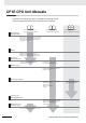
CP1E CPU Unit Manuals Information on the CP1E CPU Units is provided in the following manuals. Refer to the appropriate manual for the information that is required. This Manual CP1E CPU Unit Hardware User’s Manual(Cat. No. W479) CP1E CPU Unit Software User’s Manual(Cat. No. W480) CP1E CPU Unit Instructions Reference Manual(Cat. No.
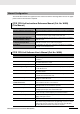
Manual Configuration The CP1E CPU manuals are organized in the sections listed in the following tables. Refer to the appropriate section in the manuals as required. CP1E CPU Unit Instructions Reference Manual (Cat. No. W483) (This Manual) Section Contents Section 1 Summary of Instructions This section provides a summary of instructions used with a CP1E CPU Unit.
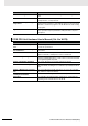
Section Contents Section 15 Analog I/O Function This section describes the built-in analog function for NA-type CPU Units. Section 16 Built-in Functions This section describes PID temperature control, clock functions, DM backup functions, security functions.
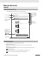
Manual Structure Page Structure and Icons The following page structure and icons are used in this manual. Installation Level 1 heading Level 2 heading Level 3 heading Installation Location Gives the current headings. 5 Installation and wiring Level 2 heading Level 3 heading 5-2 5-2-1 DIN Track Installation 1 Use a screwdriver to pull down the DIN Track mounting pins from the back of the Units to release them, and mount the Units to the DIN Track. Indicates a step in a procedure.
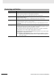
Terminology and Notation Term E-type CPU Unit Description A basic model of CPU Unit that support basic control applications using instructions such as basic, movement, arithmetic, and comparison instructions. Basic models of CPU Units are called “E-type CPU Units” in this manual. N-type CPU Unit An application model of CPU Unit that supports connections to Programmable Terminals, inverters, and servo drives. Application models of CPU Units are called “N-type CPU Units” in this manual.
Sections in this Manual 1 2 1 Summary of Instructions 3 2 Instructions 4 3 Instruction Execution Times and Number of Steps 4 Monitoring and Computing the Cycle Time A Appendices CP1E CPU Unit Instructions Reference Manual(W483) A 7
CONTENTS Introduction ............................................................................................................... 1 CP1E CPU Unit Manuals ...........................................................................................2 Manual Structure ....................................................................................................... 5 Safety Precautions ..................................................................................................
CNTR/CNTRX ......................................................................................................................................... 2-83 CNR/CNRX .............................................................................................................................................. 2-86 Comparison Instructions .............................................................................................................. 2-88 =, <>, <, <=, >, >= ........................................
XORW/XORL ......................................................................................................................................... 2-214 COM/COML ........................................................................................................................................... 2-216 Special Math Instructions ........................................................................................................... 2-218 APR ..........................................................
Other Instructions........................................................................................................................ 2-398 STC/CLC ............................................................................................................................................... 2-398 WDT ......................................................................................................................................................
Read and Understand this Manual Please read and understand this manual before using the product. Please consult your OMRON representative if you have any questions or comments. Warranty and Limitations of Liability WARRANTY OMRON’s exclusive warranty is that the products are free from defects in materials and workmanship for a period of one year (or other period if specified) from date of sale by OMRON.
Application Considerations SUITABILITY FOR USE OMRON shall not be responsible for conformity with any standards, codes, or regulations that apply to the combination of products in the customer’s application or use of the products. At the customer’s request, OMRON will provide applicable third party certification documents identifying ratings and limitations of use that apply to the products.
Disclaimers CHANGE IN SPECIFICATIONS Product specifications and accessories may be changed at any time based on improvements and other reasons. It is our practice to change model numbers when published ratings or features are changed, or when significant construction changes are made. However, some specifications of the products may be changed without any notice. When in doubt, special model numbers may be assigned to fix or establish key specifications for your application on your request.
Safety Precautions Definition of Precautionary Information The following notation is used in this manual to provide precautions required to ensure safe usage of a CP-series PLC. The safety precautions that are provided are extremely important to safety. Always read and heed the information provided in all safety precautions. WARNING Indicates an imminently hazardous situation which, if not avoided, will result in death or serious injury. Additionally, there may be severe property damage.
Caution Be sure to sufficiently confirm the safety at the destination when you transfer the program or I/O memory or perform procedures to change the I/O memory. Devices connected to PLC outputs may incorrectly operate regardless of the operating mode of the CPU Unit.
Caution Program so that the memory area of the start address is not exceeded when using a word address or symbol for the offset. For example, write the program so that processing is executed only when the indirect specification does not cause the final address to exceed the memory area by using an input comparison instruction or other instruction.
Precautions for Safe Use Observe the following precautions when using a CP-series PLC. Handling • To initialize the DM Area, back up the initial contents for the DM Area to backup memory using one of the following methods. • Set the number of words of the DM Area to be backed up starting with D0 in the Number of CH of DM for backup Box in the Startup Data Read Area. • Include programming to back up specified words in the DM Area to built-in EEPROM by turning ON A751.15 (DM Backup Save Start Bit).
Regulations and Standards Trademarks SYSMAC is a registered trademark for Programmable Controllers made by OMRON Corporation. CX-One is a registered trademark for Programming Software made by OMRON Corporation. Windows is a registered trademark of Microsoft Corporation. Other system names and product names in this document are the trademarks or registered trademarks of their respective companies.
Related Manuals The following manuals are related to the CP1E. Use them together with this manual. Manual name Cat. No. SYSMAC CP Series CP1E CPU Unit Instructions Reference Manual (this manual) W483 SYSMAC CP Series CP1E CPU Unit Software User’s Manual W480 Model numbers CP1E-E D - CP1E-N D - CP1E-NA D - CP1E-E D - CP1E-N D - CP1E-NA D - Application Contents To learn programming instructions in detail Describes each programming instruction in detail.
1 Summary of Instructions This section provides a summary of instructions used with a CP1E CPU Unit. 1-1 Summary of Instructions . . . . . . . . . . . . . . . . . . . . . . . . . . . . . . . . . . . . . . . .
1 Summary of Instructions 1-1 Summary of Instructions There are 200 types of instructions can be used by CP1E. The following table lists the instructions by function. Refer to the reference pages for the detail of each instruction. Instrucion Type Sequence Input Instructions Instruction LOAD FUN No. Function Page Indicates a logical start and creates an ON/OFF execution condition based on the ON/OFF status of the specified operand bit.
1 Summary of Instructions Sequence Output Instructions Instruction OUTPUT Mnemonic FUN No. OUT - !OUT - OUT NOT - !OUT NOT - TR Bits TR - KEEP KEEP OUTPUT NOT Function 1-1 Summary of Instructions Instrucion Type Page Outputs the result (execution condition) of the logical processing to the specified bit. 2-18 Reverses the result (execution condition) of the logical processing, and outputs it to the specified bit.
1 Summary of Instructions Instrucion Type Sequence Control Instructions Timer and Counter Instructions Instruction Mnemonic Function Page END END 001 Indicates the end of a program. 2-38 NO OPERATION NOP 000 This instruction has no function. (No processing is performed for NOP(000).) 2-39 INTERLOCK IL 002 Interlocks all outputs between IL(002) and ILC(003) when the execution condition for IL(002) is OFF.
1 Summary of Instructions Comparison Instructions Instruction Mnemonic Symbol Comparison = , <> , < , <= , > , >= Time Comparison UNSIGNED COMPARE FUN No. Function Page 300 ∼ 328 Symbol comparison instructions compare two values and create an ON execution condition when the comparison condition is true. 2-88 LD, AND, OR+=DT 341 Time comparison instructions compare two BCD time values and create an ON execution condition when the comparison condition is true.
1 Summary of Instructions Instrucion Type Data Shift Instructions Increment/ Decrement Instructions 1-6 Instruction Mnemonic FUN No. Function Page SHIFT REGISTER SFT 010 Operates a shift register. 2-127 REVERSIBLE SHIFT REGISTER SFTR/ @SFTR 084 Creates a shift register that shifts data to either the right or the left. 2-129 WORD SHIFT WSFT/ @WSFT 016 Shifts data between St and E in word units.
1 Summary of Instructions Symbol Math Instructions Instruction Mnemonic FUN No. Function Page SIGNED BINARY ADD WITHOUT CARRY +/ @+ 400 Adds 4-digit (single-word) hexadecimal data and/or constants. 2-158 DOUBLE SIGNED BINARY ADD WITHOUT CARRY +L/ @+L 401 Adds 8-digit (double-word) hexadecimal data and/or constants. 2-158 SIGNED BINARY ADD WITH CARRY +C/ @+C 402 Adds 4-digit (single-word) hexadecimal data and/or constants with the Carry Flag (CY).
1 Summary of Instructions Instrucion Type Conversion Instructions Logic Instructions Special Math Instructions 1-8 Instruction Mnemonic FUN No. Function Page BCD TO BINARY BIN/ @BIN 023 Converts BCD data to binary data. 2-185 DOUBLE BCD TO DOUBLE BINARY BINL/ @BINL 058 Converts 8-digit BCD data to 8-digit hexadecimal (32-bit binary) data. 2-185 BINARY TO BCD BCD/ @BCD 024 Converts a word of binary data to a word of BCD data.
1 Summary of Instructions Floating-point Math Instructions Instruction Data Control Instructions Subroutine Instructions Interrupt Control Instructions FUN No. Function Page FLOATING TO 16-BIT FIX/ @FIX 450 Converts a 32-bit floating-point value to 16-bit signed binary data and places the result in the specified result word. 2-233 FLOATING TO 32-BIT FIXL/ @FIXL 451 Converts a 32-bit floating-point value to 32-bit signed binary data and places the result in the specified result words.
1 Summary of Instructions Instrucion Type High-speed Counter and Pulse Output Instructions Instruction Mnemonic FUN No. Function Page MODE CONTROL INI/ @INI 880 INI(880) is used to start and stop target value comparison, to change the present value (PV) of a high-speed counter, to change the PV of an interrupt input (counter mode), to change the PV of a pulse output, or to stop pulse output.
1 Summary of Instructions Other Instructions Instruction Mnemonic FUN No. Function Page SET CARRY STC/ @STC 040 Sets the Carry Flag (CY). 2-398 CLEAR CARRY CLC/ @CLC 041 Turns OFF the Carry Flag (CY). 2-398 EXTEND MAXIMUM CYCLE TIME WDT/ @WDT 094 Extends the maximum cycle time, but only for the cycle in which this instruction is executed.
1 Summary of Instructions 1-12 CP1E CPU Unit Instructions Reference Manual(W483)
2 Instructions This section describes the functions, operands and sample programs of the instructions that are supported by a CP1E CPU Unit. Notation and Layout of Instruction Descriptions . . . . . . . . . . . . . . . . . . . . 2-2 Sequence Input Instructions . . . . . . . . . . . . . . . . . . . . . . . . . . . . . . . . . . . . . 2-5 Sequence Output Instructions . . . . . . . . . . . . . . . . . . . . . . . . . . . . . . . . . . 2-18 Sequence Control Instructions . . . . . . . . . . . . . . . . . . . .
2 Instructions Notation and Layout of Instruction Descriptions Instructions are described in groups by function. Refer to Appendix A List of Instructions by Function Code for a list of instructions by mnemonic that lists the page number in this section for each instruction. The description of each instruction is organized as described in the following table. Item Contents Instruction Indicates the name of the instruction. Example: MOVE BIT Mnemonic Indicates the mnemonic.
2 Instructions Item Contents Flags Name Function Label Notation and Layout of Instruction Descriptions The flags table indicates the status of the condition flags immediately after execution of the instruction. Any flags that are not listed are not affected by the instruction. “OFF” indicates that a flag is turned OFF immediately after execution of the instruction regardless of the results of executing the instruction.
2 Instructions Condition Flags With the CX-Programmer, the condition flags are registered in advance as global symbols with “P_” in front of the symbol name.
2 Instructions Differentiated and Immediate Refreshing Instructions • The LOAD, AND, and OR instructions have differentiated and immediate refreshing variations in addition to their ordinary forms, and there are also two combinations available. • The LOAD NOT, AND NOT, OR NOT, OUT, and OUT NOT instructions have immediate refreshing variations in addition to their ordinary forms.
2 Instructions Operation Timing for I/O Instructions The following chart shows the differences in the timing of instruction operations for a program configured from LD and OUT.
2 Instructions Instruction Mnemonic LOAD LOAD NOT Function code Variations Function LD @LD, %LD, !LD, !@LD, !%LD --- Indicates a logical start and creates an ON/OFF execution condition based on the ON/OFF status of the specified operand bit. LD NOT @LD NOT, %LD NOT, ! LD NOT, !@LD NOT, !%LD NOT --- Indicates a logical start and creates an ON/OFF execution condition based on the reverse of the ON/OFF status of the specified operand bit.
2 Instructions Hint • LD/LD NOT is used in the following circumstances as an instruction for indicating a logical start. 1. When directly connecting to the bus bar. 2. When logic blocks are connected by AND LD or OR LD, i.e., at the beginning of a logic block. The AND LOAD and OR LOAD instructions are used to connect in series or in parallel logic blocks beginning with LD or LD NOT.
2 Instructions Instruction Mnemonic AND AND NOT Variations Function code Function AND @AND, %AND, !AND, !@AND, !%AND --- Takes a logical AND of the status of the specified operand bit and the current execution condition. AND NOT @AND NOT, %AND NOT, !AND NOT, !@AND NOT, !%AND NOT --- Reverses the status of the specified operand bit and takes a logical AND with the current execution condition.
2 Instructions Precautions • Differentiate up (@) or differentiate down (%) can be specified for AND. If differentiate up (@) is specified, the execution condition is turned ON for one cycle only after the status of the operand bit goes from OFF to ON. If differentiate down (%) is specified, the execution condition is turned ON for one cycle only after the status of the operand bit goes from ON to OFF. • Immediate refreshing (!) can be specified for AND/AND NOT.
2 Instructions Instruction Mnemonic OR OR NOT Function code Variations Function OR @OR, %OR, !OR, !@OR, !%OR --- Takes a logical OR of the ON/OFF status of the specified operand bit and the current execution condition. OR NOT @OR NOT, %OR NOT, !OR NOT, !@OR NOT, !%OR NOT --- Reverses the status of the specified bit and takes a logical OR with the current execution condition.
2 Instructions Precautions • Differentiate up (@) or differentiate down (%) can be specified for OR. If differentiate up (@) is specified, the execution condition is turned ON for one cycle only after the status of the operand bit goes from OFF to ON. If differentiate down (%) is specified, the execution condition is turned ON for one cycle only after the status of the operand bit goes from ON to OFF. • Immediate refreshing (!) can be specified for OR/OR NOT.
2 Instructions Instruction Mnemonic Function code Variations Sequence Input Instructions AND LD/OR LD Function AND LOAD AND LD --- --- Takes a logical AND between logic blocks. OR LOAD OR LD --- --- Takes a logical OR between logic blocks. AND LD OR LD Logic block Symbol Logic block Logic block 2 Logic block AND LD/OR LD Applicable Program Areas Area Step program areas Subroutines Interrupt tasks Usage OK OK OK Flags There are no flags affected by this instruction.
2 Instructions Precautions When a logic block is connected by AND LOAD or OR LOAD instructions, the total number of AND LOAD/OR LOAD instructions must match the total number of LOAD/LOAD NOT instructions minus 1. If they do not match, a programming error will occur. AND LD In the following diagram, the two logic blocks are indicated by dotted lines. Studying this example shows that an ON execution condition will be produced when either of the execution conditions in the left logic block is ON (i.e.
2 Instructions Sample program i 0.00 0.02 0.04 0.01 0.03 0.05 100.00 Coding Example (1) Instruction Coding Example (2) Operand Instruction Operand LD 0.00 LD 0.00 OR NOT 0.01 OR NOT 0.01 LD NOT 0.02 LD NOT 0.02 OR 0.03 OR 0.03 AND LD --- LD 0.04 LD 0.04 OR 0.05 OR 0.05 AND LD --- . . . . . . . . AND LD --- AND LD --- OUT 100.00 . . . . OUT 100.00 2 AND LD/OR LD • The AND LOAD instruction can be used repeatedly.
2 Instructions NOT Instruction Mnemonic NOT NOT Variations Function code --- 520 Function Reverses the execution condition. NOT Symbol NOT(520) Applicable Program Areas Area Step program areas Subroutines Interrupt tasks Usage OK OK OK Flags There are no flags affected by NOT(520). Function NOT(520) is placed between an execution condition and another instruction to invert the execution condition. Precautions NOT(520) is an intermediate instruction, i.e.
2 Instructions Instruction Mnemonic Variations Function code Function CONDITION ON UP --- 521 UP(521) turns ON the execution condition for the next instruction for one cycle when the execution condition it receives goes from OFF to ON. CONDITION OFF DOWN --- 522 DOWN(522) turns ON the execution condition for the next instruction for one cycle when the execution condition it receives goes from ON to OFF.
2 Instructions Sequence Output Instructions OUT/OUT NOT Instruction Mnemonic OUTPUT OUT OUTPUT NOT OUT NOT Variations Function code !OUT --- !OUT NOT --- Function Outputs the result (execution condition) of the logical processing to the specified bit. Reverses the result (execution condition) of the logical processing, and outputs it to the specified bit.
2 Instructions Hint • Difference between SET/RSET and OUT For OUT, the operand bit is turned ON when the input condition turns ON and is turned OFF when the input condition turns OFF. For SET and RSET, the operand bit turns ON or OFF, respectively, when the input condition turns ON and the operand bit does not change when the input condition turns OFF. Sample program 2 100.00 0.00 Sequence Output Instructions • Immediate refreshing (!) can be specified for OUT and OUT NOT.
2 Instructions TR Instruction Mnemonic TR Bits Variations Function code Function --- --- TR bits are used to temporarily retain the ON/OFF status of execution conditions in a program when programming in mnemonic code. TR Function TR bits are used to temporarily retain the ON/OFF status of execution conditions in a program when programming in mnemonic code. They are not used when programming directly in ladder program form because the processing is automatically executed by the Peripheral Device.
2 Instructions Instruction Mnemonic KEEP KEEP Variations Function code !KEEP 011 Sequence Output Instructions KEEP Function Operates like a latching relay.
2 Instructions Hint • KEEP(011) has an immediate refreshing variation (!KEEP(011)). When a CPU Unit built-in output bit has been specified for R in a !KEEP(011) instruction, any changes to R will be refreshed when !KEEP(011) is executed and reflected immediately in the output bit. • KEEP(011) operates like the self-maintaining bit, but a self-maintaining bit programmed with KEEP(011) requires one less instruction. 0.02 100.00 0.03 5.00 0.02 KEEP 100.00 0.
2 Instructions 0.02 KEEP H0.00 0.03 Indicates emergency situation 0.04 0.05 H0.00 Sequence Output Instructions • If a holding bit is used for R, the bit status will be retained even during a power interruption. KEEP(011) can thus be used to program bits that will maintain status after restarting the PLC following a power interruption. An example of this that can be used to produce a warning display following a system shutdown for an emergency situation is shown below.
2 Instructions Sample program 0.00 KEEP 100.00 0.01 0.02 When CIO 0.00 goes ON in the left example, CIO 100.00 is turned ON. CIO 100.00 remains ON until CIO 0.01 goes ON. When CIO 0.02 goes ON and CIO 0.03 goes OFF in the left example, CIO 100.01 is turned ON. CIO 100.01 remains ON until CIO 0.04 or CIO 0.05 goes ON. 0.03 KEEP 100.01 0.04 0.05 Coding Instruction Operand LD 0.00 LD 0.01 KEEP (011) 100.00 LD 0.02 AND NOT 0.03 LD 0.04 OR 0.05 KEEP (011) 100.
2 Instructions Instruction Mnemonic DIFFERENTIATE UP DIFU Variations Function code !DIFU 013 Function DIFU(013) turns the designated bit ON for one cycle when the execution condition goes from OFF to ON (rising edge).
2 Instructions Precautions • The operation of DIFU(013) depends on the execution condition for the instruction itself as well as the execution condition for the program section when it is programmed in an interlocked program section, a jumped program section, or a subroutine. • An subroutine will not be executed while the input condition for the subroutine is OFF. Caution is thus required when using DIFU(013) in a function block definition. For details, refer to information on SBS(091).
2 Instructions Instruction Mnemonic DIFFERENTIATE DOWN DIFD Variations Function code Function !DIFD 014 DIFD(014) turns the designated bit ON for one cycle when the execution condition goes from ON to OFF (falling edge).
2 Instructions Precautions • The operation of DIFD(014) will not be consistent if the same function block instance is executed more than once in the same cycle. • An subroutine will not be executed while the input condition for the subroutine is OFF. Caution is thus required when using DIFD(014) in a function block definition. For details, refer to information on SBS(091). Sample program When CIO 0.00 goes from ON to OFF in the following example, CIO 100.00 is turned ON for one cycle. i 0.00 DIFD 100.
2 Instructions Instruction Mnemonic SET RESET Variations SET @SET, %SET, !SET, !@SET, !%SET RSET @RSET, %RSET, !RSET, !@RSET, !%RSET Function code Function --- SET turns the operand bit ON when the execution condition is ON. After this, the specified contact will remain ON regardless of ON/OFF of the input condition. --- RSET turns the operand bit OFF when the execution condition is ON. After this, the specified contact will remain OFF regardless of ON/OFF of the input condition.
2 Instructions Hint • Differences between OUT/OUT NOT and SET/RSET The operation of SET differs from that of OUT because the OUT instruction turns the operand bit OFF when its execution condition is OFF. Likewise, RSET differs from OUT NOT because OUT NOT turns the operand bit ON when its execution condition is OFF. For OUT, the operand bit is turned ON when the input condition turns ON and is turned OFF when the input condition turns OFF.
2 Instructions Instruction Mnemonic Function code Variations Function MULTIPLE BIT SET SETA @SETA 530 SETA(530) turns ON the specified number of consecutive bits. MULTIPLE BIT RESET RSTA @RSTA 531 RSTA(531) turns OFF the specified number of consecutive bits.
2 Instructions RSTA N1 RSTA(531) turns OFF N2 bits, beginning from bit N1 of D, and continuing to the left (more-significant bits). All other bits are left unchanged. (No changes will be made if N2 is set to 0.) 15 0 D 0 0 0 D+1 0 0 0 D+2 N2 bits are reset to 0 (OFF). 0 Bits turned OFF by RSTA(531) can be turned ON by any other instructions, not just SETA(530). Hint SETA • SETA(530) can be used to turn ON bits in data areas that are normally accessed by words only, such as the DM areas.
2 Instructions Instruction Mnemonic Function code Variations Function SINGLE BIT SET SETB @SETB, !SETB, !@SETB 532 SETB(532) turns ON the specified bit. SINGLE BIT RESET RSTB @RSTB, !RSTB, !@RSTB 533 RSTB(533) turns OFF the specified bit.
2 Instructions RSTB 15 RSTB(533) turns OFF bit N of word D when the execution condition is ON. The status of the bit is not affected when the execution condition is OFF. (Use SETB(532) to turn ON the bit.) This bit is turned OFF. Execution condition ON OFF Bit N of word D ON OFF Hint • Differences between SET/RSET and SETB(532)/RSTB(533) The instructions operate in the same way when the specified bit is in the CIO, W, H, or A Area.
2 Instructions Overview of Interlock Instructions Interlock Instructions The following instruction combinations can be used to interlock outputs in a program section. • INTERLOCK and INTERLOCK CLEAR (IL(002) and IL(003)) • MULTI-INTERLOCK DIFFERENTIATION HOLD and MULTI-INTERLOCK CLEAR (MILH(517) and MILC(519))* Note MILH(517) holds the status of the Differentiation Flag, so differentiated instructions that were interlocked are executed after the interlock is cleared.
2 Instructions Differences between MILH(517) and MILR(518) Differentiated instructions (DIFU, DIFD, or instructions with a @ or % prefix) operate differently in interlocks created with MILH(517) and MILR(518). The operation of differentiated instructions in an interlock created with MILH(517) is identical to the operation in an interlock created with IL(002).
2 Instructions Differences between Interlocks and Jumps Instruction execution Except OUT, OUT NOT, and timer instructions, all instructions are not executed. No instructions are executed. Output status in instructions Except for outputs in OUT, OUT NOT, and timer instructions, all outputs retain their previous status. All outputs retain their previous status. Sequence Control Instructions Bits in OUT, OUT NOT OFF All outputs retain their previous status.
2 Instructions END Instruction END Mnemonic END Variations Function code --- 001 Function Indicates the end of a program. END Symbol END(001) Applicable Program Areas Area Step program areas Subroutines Interrupt tasks Usage Not allowed Not allowed OK Flags There are no flags affected by this instruction. Function END(001) completes the execution of a program for that cycle. No instructions written after END(001) will be executed.
2 Instructions Instruction NO OPERATION Mnemonic NOP Variations Function code --- 000 Sequence Control Instructions NOP Function This instruction has no function. NOP Symbol (There is no ladder symbol associated with NOP(000).) Applicable Program Areas Area Step program areas Subroutines Interrupt tasks Usage OK OK OK 2 Flags NOP No flags are affected by NOP(000).
2 Instructions IL/ILC Instruction Mnemonic Variations Function code Function INTERLOCK IL --- 002 Interlocks all outputs between IL(002) and ILC(003) when the execution condition for IL(002) is OFF. INTERLOCK CLEAR ILC --- 003 Indicates the end of the interlock range. IL Symbol ILC ILC(003) IL(002) Applicable Program Areas Area Step program areas Subroutines Interrupt tasks Usage Not allowed OK OK Flags There are no flags affected by this instruction.
2 Instructions Hint Sequence Control Instructions • If there are bits which you want to remain ON in an interlocked program section, set these bits to ON with SET just before IL(002). IL A A • It is often more efficient to switch a program section with IL(002) and ILC(003). When several processes are controlled with the same execution condition, it takes fewer program steps to put these processes between IL(002) and ILC(003).
2 Instructions Operation of Differentiated Instructions If there is a differentiated instruction (DIFU, DIFD, or instruction prefixed by @ or %) between IL(002) and ILC(003) instructions, that instruction will be executed when the interlock is cleared if the differentiation condition of the instruction is satisfied by means of a change in the input condition between starting and clearing of the interlock.
2 Instructions Sample program 0.00 0.00 ON Sequence Control Instructions When CIO 0.00 is OFF in the right example, all outputs between IL(002) and ILC(003) are interlocked. When CIO 0.00 is ON in the right example, the instructions between IL(002) and ILC(003) are executed normally. 0.00 OFF IL 0.01 2.00 OFF 0.02 H0 OFF TIM 2 Outputs interlocked Normal execution Reset IL/ILC SET Retained 0.
2 Instructions MILH/MILR/MILC Instruction Mnemonic Variations Function code Function MULTI-INTERLOCK DIFFERENTIATION HOLD MILH --- 517 Interlocks all outputs between MILH(517) and MILC(519) when the execution condition for MILH(517) is OFF. MULTI-INTERLOCK DIFFERENTIATION RELEASE MILR --- 518 Interlocks all outputs between MILR(518) and MILC(519) when the execution condition for MILR(518) is OFF.
2 Instructions Function Interlock Status The following table shows the treatment of various outputs in an interlocked section between MILH(517)/MILR(518) instruction and the next MILC(519). Instruction Bits specified in OUT, OUT NOT 2 OFF Completion Flag PV OFF (reset) Time set value (reset) Bits/words specified in all other instructions (See note.) Retain previous status.
2 Instructions • A1 and A2 are interlocked when the Emergency Stop Button is ON. Global interlock (Emergency stop) MILH • A2 is interlocked when Conveyor RUN is OFF. 0 A1 (Peripheral processing) When the Emergency Stop is ON (input condition OFF), both A1 and A2 are interlocked. When the Emergency Stop is OFF (input condition ON), A1 is executed normally and A2 is controlled by the Conveyor RUN switch as described below.
2 Instructions Differentiated instructions (DIFU, DIFD, or instructions with a @ or % prefix) operate differently in interlocks created with MILH(517) and MILR(518). When a program section is interlocked with MILR(518), a differentiated instruction will not be executed when the interlock is cleared even if the differentiation condition was activated during the interlock (comparing the status of the execution condition when the interlock started to its status when the interlock was cleared).
2 Instructions Operation of Differentiated Instructions in an MILR(518) Interlock If there is a differentiated instruction (DIFU, DIFD, or instruction with a @ or % prefix) between MILR(518) and the corresponding MILC(519), that instruction will not be executed after the interlock is cleared even if the differentiation condition of the instruction was established.
2 Instructions Hint • When nesting interlocks, assign interlock numbers so that the nested program section does not exceed the outer program section.
2 Instructions • If there is an ILC(003) instruction between an MILR(518) and MILC(519) pair, the ILC(003) instruction will be ignored and the full program section between MILR(518) and MILC(519) will be interlocked. a MILR 0 When input condition “a” is OFF, program sections A1 and A2 are interlocked. A1 ILC The ILC(003) instruction is ignored.
2 Instructions a a MILH A1 0 b A2 A1 b MILH 1 Sequence Control Instructions • Program operation can be switched more efficiently by using interlocks with MILH(517) or MILR(518). Instead of switching processing with compound conditions, insert an MILH(517) or MILR(518) instruction before each process and an MILC(519) instruction after each process.
2 Instructions Sample program When W0.00 and W0.01 are both ON, the instructions between MILH(517) with interlock number 0 and MILC(519) with interlock number 0 are executed normally. When W0.00 is OFF, the instructions between MILH(517) with interlock number 0 and MILC(519) with interlock number 0 are interlocked. When W0.00 is ON and W0.01 are OFF, the instructions between MILH(517) with interlock number 1 and MILC(519) with interlock number 1 are interlocked.
2 Instructions Instruction Mnemonic JUMP Variations JMP --- Function code Function 004 When the execution condition for JMP(004) is OFF, program execution jumps directly to the first JME(005) in the program with the same jump number. CONDITIONAL JUMP CJP --- 510 When the execution condition for CJP(510) is ON, program execution jumps directly to the first JME(005) in the program with the same jump number.
2 Instructions Function JMP When the execution condition for JMP(004) is ON, no jump is made and the program is executed consecutively as written. When the execution condition for JMP(004) is OFF, program execution jumps directly to the first JME(005) in the program with the same jump number. The instructions between JMP(004) and JME(005) are not executed, so the status of outputs between JMP(004) and JME(005) is maintained.
2 Instructions JME N Program section A is executed repeatedly as long as execution condition a is OFF. A Sample program When CIO 0.00 is OFF in the right example, the instructions between JMP(004) and JME(005) are not executed and the outputs maintain their previous status. When CIO 0.00 is ON in the right example, the instructions between JMP(004) and JME(005) are executed normally. 0.00 JMP &1 &1 CIO 0.00 ON Normal execution TIM CIO 0.00 OFF Instructions not executed. (Outputs remain unchanged.
2 Instructions FOR/NEXT Variations Function code FOR --- 512 NEXT --- 513 Instruction Mnemonic Function The instructions between FOR(512) and NEXT(513) are repeated a specified number of times.
2 Instructions Hint • FOR-NEXT Loop with BREAK Start a FOR-NEXT loop with a maximum of N repetitions. Program BREAK(514) within the loop with the desired execution condition. The loop will end before N repetitions if the execution condition is input. • JME(005)-JMP(004) Loop Program a loop with JME(005) before JMP(004). The instructions between JME(005) and JMP(004) will be executed repeatedly as long as the execution condition for JMP(004) is OFF.
2 Instructions FOR FOR &3 &3 &3 Escapes from loop when condition a is ON. BREAK a FOR Remaining &2 instructions are processed as NEXT NOP(000). Breaks FOR-NEXT loop 2. 1 2 BREAK NEXT Breaks FOR-NEXT loop 1. BREAK NEXT • A jump instruction such as JMP(004) may be executed within a FOR-NEXT loop, but do not jump beyond the FOR-NEXT loop. • The following instructions cannot be used within FOR-NEXT loops: • STEP DEFINE and STEP START: STEP(008)/SNXT(009) Sample program FOR &3 Repeated 3 times.
2 Instructions Instruction BREAK LOOP Mnemonic Variations BREAK --- Function code 514 Function Programmed in a FOR-NEXT loop to cancel the execution of the loop for a given execution condition. The remaining instructions in the loop are processed as NOP(000) instructions.
2 Instructions Timer and Counter Instructions Refresh Methods for Timer/Counter PV Overview There are two PV refresh methods for instructions related to timer/counters, “BCD” and “BINARY”. Method Description BCD Binary Setting range Set value Sets the timer set value in BCD. 0~9.999 #0000~9999 Sets the timer set value in BINARY. 0~65.535 &0~65535 or #0000~FFFF The PLC Setup for all of the timer/counter-related instructions. The refresh method is valid also when setting an SV indirectly (i.e.
2 Instructions Item TIM/TIMX (550) TIMH(015)/ TIMHX(551) TMHH(540)/ TMHHX(552) TTIM(087)/ TTIMX(555) TIML(542)/ TIMLX(553) Operating mode change PV = 0 Completion Flag = OFF --- Power interrupt/reset PV = 0 Completion Flag = OFF --- Execution of CNR(545)/CNRX(547) Binary: PV = FFFF, Completion Flag = OFF BCD: PV = FFFF or 9999, Completion Flag = OFF Not applicable Operation in jumped program section (JMP(004)-JME(005)) Operating timers continue timing. Timer status is maintained.
2 Instructions Example Timer and Counter Applications Example 1: Long-term Timers The following program examples show three ways to create long-term timers with standard TIM and CNT instructions. 1) Two TIM Instructions In this example, two TIM instructions are combined to make a 30-minute timer. 0.00 (900 seconds) TIM Instruction Operands 0001 LD 0.00 #9000 TM 1 T0001 #9000 (900 seconds) TIM LD 0002 #9000 100.00 T0002 T0001 TM 2 #9000 LD T000 OUT 100.
2 Instructions Example 2: Two-stage Counter 0.00 0.01 CNT Instruction Operands LD 0.00 (100 times) 0001 0.02 AND 0.01 LD NOT 0.02 OR C0001 OR C0002 #0100 C0001 CNT 1 C0002 #0100 C0001 CNT LD C0001 LD NOT 0.02 (200 times) CNT #0200 #0200 100.03 C0002 2 2 0002 0.02 LD C0002 OUT 100.03 Example 3: ON/OFF Delay In this example two TIM timers are combined with KEEP(011) to make an ON delay and an OFF delay. CIO 5.00 will be turned ON 5.0 seconds after CIO 0.
2 Instructions Example 4: One-shot Bit A TIM timer can be combined with OUT or OUT NOT to control how long a particular bit is ON or OFF. In this example, CIO 2.04 will be ON for 1.5 seconds (the SV of T0001) after CIO 0.00 goes ON. 10.00 0.00 10.00 Instruction 0.00 LD 10.00 AND NOT 100.00 100.00 OR LD -- OUT 10.00 0001 LD 10.00 #0015 TIM 10.00 TIM (1.5seconds) 1 #0015 100.00 T0001 10.00 Operands LD 100.04 100.00 LD T0001 OUT 100.00 LD 10.00 AND NOT 100.00 OUT 100.
2 Instructions 2) Clock Pulse 0.00 P. 1s (1-s clock pulse) 0.00 100.06 Instruction Operands LD 0.00 AND 1s OUT 100.06 • The internal clock pulse (0.1 s, 0.2 s, 1 s) can be used to easily program a flicker circuit. 1s A B Timer and Counter Instructions The desired execution condition can be combined with a clock pulse to mimic the clock pulse (0.1 s, 0.2 s, or 1.0 s). 100.06 2 A,B=0.5s Timer reset method There are two methods for resetting a timer instruction. 1.
2 Instructions TIM/TIMX Instruction Mnemonic HUNDRED-MS TIMER Variations Function code Function --- 550 TIM or TIMX(550) operates a decrementing timer with units of 0.1-s.
2 Instructions • When the timer input is OFF, the timer specified by N is reset, i.e., the timer’s PV is reset to the SV and its Completion Flag is turned OFF. • When the timer input goes from OFF to ON, TIM/TIMX(550) starts decrementing the PV. The PV will continue timing down as long as the timer input remains ON and the timer’s Completion Flag will be turned ON when the PV reaches 0. • The setting range for the set value (SV) is 0 to 999.9 s for TIM and 0 to 6,553.5 s for TIMX(550).
2 Instructions Condition PV Completion Flag Operating mode changed from RUN or MONITOR mode to PROGRAM mode or vice versa.*1 0 OFF Power off and reset 0 OFF Execution of CNR(545)/CNRX(547), the RESET TIMER/COUNTER instructions*2 BCD: 9999 Binary: FFFF OFF Operation in interlocked program section (IL(002)–ILC(003)) Reset to SV. OFF Operation in jumped program section (JMP(004)–JME(005)) Retains previous status. Retains previous status. *1 If the IOM Hold Bit (A500.
2 Instructions Variations Function code TIMH --- 015 TIMHX --- 551 Instruction Mnemonic TEN-MS TIMER Function TIMH(015)/TIMHX(551) operates a decrementing timer with units of 10-ms.
2 Instructions Function • When the timer input is OFF, the timer specified by N is reset, i.e., the timer’s PV is reset to the SV and its Completion Flag is turned OFF. • When the timer input goes from OFF to ON, TIMH(015)/TIMHX(551) starts decrementing the PV. The PV will continue timing down as long as the timer input remains ON and the timer’s Completion Flag will be turned ON when the PV reaches 0000. • The status of the timer’s PV and Completion Flag will be maintained after the timer times out.
2 Instructions PV Completion Flag 0 OFF Power off and reset 0 OFF Execution of CNR(545)/CNRX(547), the RESET TIMER/COUNTER instructions*2 BCD: 9999 Binary: FFFF OFF Operation in interlocked program section (IL(002)-ILC(003)) Reset to SV. OFF Operation in jumped program section Retains previous status. Retains previous status. (JMP(004)-JME(005)) Timer and Counter Instructions Condition Operating mode changed from RUN or MONITOR mode to PROGRAM mode or vice versa.
2 Instructions TMHH/TMHHX Instruction Variations Function code TMHH --- 540 TMHHX --- 552 Mnemonic ONE-MS TIMER Function TMHH(540)/TMHHX(552) operates a decrementing timer with units of 1-ms.
2 Instructions • The timer accuracy is -0.01 to 0 s. Hint The timer PV and timeup used in TMHH/TMHHX instructions are refreshed at the timing below. Refresh timing When each instruction is executed Description • The PV is updated every time that each instruction is executed. • The timeup flag is ON when the PV is 0 and OFF otherwise. Precautions • The Completion Flag is updated only when TMHH(540)/TMHHX(552) is executed.
2 Instructions TTIM/TTIMX Instruction Variations Function code TTIM --- 087 TTIMX --- 555 Mnemonic ACCUMULATIVE TIMER Function TTIM(087)/TTIMX(555) operates an incrementing timer with units of 0.1-s.
2 Instructions • When the timer input is ON, TTIM(087)/TTIMX(555) increments the PV. When the timer input goes OFF, the timer will stop incrementing the PV, but the PV will retain its value. The PV will resume timing when the timer input goes ON again. The timer’s Completion Flag will be turned ON when the PV reaches the SV. SV Timer PV Timing resumes. PV maintained.
2 Instructions • When a TTIM(087)/TTIMX(555) timer is forced set, its Completion Flag will be turned ON and its PV will be reset to 0. When a TTIM(087)/TTIMX(555) timer is forced reset, its Completion Flag will be turned OFF and its PV will be reset to 0. The forced set and forced reset operations take priority over the status of the timer and reset inputs.
2 Instructions Variations Function code TIML --- 542 TIMLX --- 553 Instruction Mnemonic LONG TIMER Function TIML(542)/TIMLX(553) operates a decrementing timer with units of 0.1s.
2 Instructions Function • When the timer input is OFF, the timer is reset, i.e., the timer’s PV is reset to the SV and its Completion Flag is turned OFF. • When the timer input goes from OFF to ON, TIML(542)/TIMLX(553) starts decrementing the PV in D2+1 and D2. The PV will continue timing down as long as the timer input remains ON and the timer’s Completion Flag will be turned ON when the PV reaches 0.
2 Instructions When timer input CIO 0.00 is ON in the following example, the timer PV (in D201 and D200) will be set to the SV (in D101 and D100) and the PV will begin counting down. The timer Completion Flag (CIO 200.00) will be turned ON when the PV reaches 0. When CIO 0.00 goes OFF, the timer PV will be reset to the SV and the Completion Flag will be turned OFF. 0.00 TIML D1 200 D2 D100 S D200 ON OFF Timer input Timer SV S: D200 and up S+1: Content of D201 1000.
2 Instructions CNT/CNTX Instruction Mnemonic COUNTER Variations Function code --- 546 CNT/CNTX Function CNT/CNTX(546) operates a decrementing counter.
2 Instructions • The counter PV is decremented by 1 every time that the count input goes from OFF to ON. The Completion Flag is turned ON when the PV reaches 0. • Once the Completion Flag is turned ON, reset the counter by turning the reset input ON or by using the CNR(545)/CNRX(547) instruction. Otherwise, the counter cannot be restarted.
2 Instructions • When a CNT/CNTX(546) counter is forced set, its Completion Flag will be turned ON and its PV will be reset to 0000. When a CNT/CNTX(546) counter is forced reset, its Completion Flag will be turned OFF and its PV will be set to the SV. • Be sure to reset the counter by turning the reset input from OFF → ON → OFF before beginning counting with the count input, as shown in the following diagram. The count input will not be received if the reset input is ON.
2 Instructions Variations Function code CNTR --- 012 CNTRX --- 548 Instruction Mnemonic REVERSIBLE COUNTER Timer and Counter Instructions CNTR/CNTRX Function --- CNTR CNTRX BCD Binary Increment input Increment input CNTR(012) Symbol Decrement input Reset input CNTRX(548) N N: Counter number S S: Set value Decrement input Reset input N N: Counter number S S: Set value CNTR/CNTRX Applicable Program Areas Area Step program areas Subroutines Interrupt tasks Usage OK OK OK
2 Instructions Function The counter PV is incremented by 1 every time that the increment input goes from OFF to ON and it is decremented by 1 every time that the decrement input goes from OFF to ON. The PV can fluctuate between 0 and the SV. When incrementing, the Completion Flag will be turned ON when the PV is incremented from the SV back to 0 and it will be turned OFF again when the PV is incremented from 0 to 1.
2 Instructions Increment input 0.01 Decrement input Timer and Counter Instructions 0.00 CNTR 0.02 0001 #0003 Increment input 0.00 Reset input 0.01 0.02 OFF ON Decrement input OFF 0.01 or 0.00 ON Increment input Reset input 0.02 CNTRX ON OFF 0001 Decrement input &3 Counter PV C0001 2 SV 3 0 Reset input The add and subtract count inputs increase/decrease the count once when the signal rises (OFF to ON). When both inputs turn ON at the same time, neither increases/decreases the count.
2 Instructions CNR/CNRX Instruction Mnemonic RESET TIMER/COUNTER Function code Variations CNR @CNR 545 CNRX @CNRX 547 Function Resets the timers or counters within the specified range of timer or counter numbers.
2 Instructions • The timer/counter that is reset is as follows. Instructions reset TIM: TIMH(015): TMHH(540): TTIM(087): CNT: CNTR(012): Binary TIMX(550): TIMHX(551): TMHHX(552): TTIMX(555): CNTX(546): CNTRX(548): HUNDRED-MS TIMER TEN-MS TIMER ONE-MS TIMER ACCUMULATIVE TIMER COUNTER REVERSIBLE COUNTER The PV is set to its maximum value (9,999 BCD) and the Completion Flag is turned OFF.
2 Instructions Comparison Instructions =, <>, <, <=, >, >= Instruction Mnemonic =, <>, <, <=, >, >= Input Comparison Instructions Function code Function 300 to 328 Input comparison instructions compare two values (constants and/or the contents of specified words) and create an ON execution condition when the comparison condition is true. Input comparison instructions are available to compare signed or unsigned data of one-word or double length data.
2 Instructions Operation Name Label Data length: one-word Data length: double length P_LT • OFF in all other cases. • OFF in all other cases. Less Than or Equal Flag P_LE • ON if S1 ≤ S2 with one-word data. • ON if S1+1, S1 ≤ S2+1, S2 with double-length data. • OFF in all other cases. • OFF in all other cases. Negative Flag P_N OFF or unchanged OFF or unchanged Function • ON if S1 < S2 with one-word data. • ON if S1+1, S1 < S2+1, S2 with double-length data.
2 Instructions Function True if C1 ≤ C2 True if C1 > C2 True if C1 ≥ C2 Mnemonic Name Code LD/AND/OR <= LESS THAN OR EQUAL LD/AND/OR<=L DOUBLE LESS THAN OR EQUAL 315 316 LD/AND/OR <=S SIGNED LESS THAN OR EQUAL 317 LD/AND/OR <=SL DOUBLE SIGNED LESS THAN OR EQUAL 318 LD/AND/OR > GREATER THAN 320 LD/AND/OR >L DOUBLE GREATER THAN 321 LD/AND/OR >S SIGNED GREATER THAN 322 LD/AND/OR >SL DOUBLE SIGNED GREATER THAN 323 LD/AND/OR >= GREATER THAN OR EQUAL 325 LD/AND/OR >=L DOUBLE GREA
2 Instructions =DT, <>DT, DT, >=DT Mnemonic Variations Function code Function --- 341 342 343 344 345 346 Time comparison instructions compare two BCD time values and create an ON execution condition when the comparison condition is true.
2 Instructions i S1 through S1+2: Present Time Data S2 through S2+2: Comparison Time Data S1 through S1+2 contain the present time data. S1 through S1+2 must be in the same data area. S2 through S2+2 contain the comparison time data. S2 through S2+2 must be in the same data area.
2 Instructions Function The time comparison instructions are treated just like the LD, AND, and OR instructions to control the execution of subsequent instructions. There are 18 possible combinations of time comparison instructions. Any time values that are masked in the control word (C) are not included in the comparison.
2 Instructions Precautions • Time comparison instructions cannot be used as right-hand instructions, i.e., another instruction must be used between them and the right bus bar. • E-type CP1E CPU Unit (CP1E-E - ) does not have the clock function. The clock data inside the CPU Unit is always 01-01-01 01:01:01. Sample program When CIO 0.00 is ON and the time is 13:00:00, CIO 100.00 is turned ON.
2 Instructions CMP/CMPL Mnemonic COMPARE Variations CMP DOUBLE COMPARE Function code Function 020 Compares two unsigned binary values (constants and/or the contents of specified words) and outputs the result to the Arithmetic Flags in the Auxiliary Area. 060 Compares two double unsigned binary values (constants and/or the contents of specified words) and outputs the result to the Arithmetic Flags in the Auxiliary Area.
2 Instructions The following table shows the status of the Arithmetic Flags after execution of CMP(020). Flag status CMP(020) Result > >= = <= < <> S 1 > S2 ON ON OFF OFF OFF ON S 1 = S2 OFF ON ON ON OFF OFF S 1 < S2 OFF OFF OFF ON ON ON * A status of “---” indicates that the Flag may be ON or OFF. Unsigned binary comparison S1 S2 Arithmetic Flags (>, >=, =, <=, <, <>) The following table shows the status of the Arithmetic Flags after execution of CMPL(060).
2 Instructions Precautions S2 Comparison Instructions • Using CMP(020)Results in the Program When CMP(020)/CMPL(060) is executed, the result is reflected in the Arithmetic Flags. Control the desired output or right-hand instruction with a branch from the same input condition that controls CMP(020)/CMPL(060), as shown in the following diagram. In this case, the Equals Flag and output A will be turned ON when S1 = S2 or S1 + 1, S1 = S2 + 1, S2.
2 Instructions CPS/CPSL Instruction Mnemonic SIGNED BINARY COMPARE DOUBLE SIGNED BINARY COMPARE Variations CPS Function code Function 114 Compares two signed binary values (constants and/or the contents of specified words) and outputs the result to the Arithmetic Flags in the Auxiliary Area. 115 Compares two double signed binary values (constants and/or the contents of specified words) and outputs the result to the Arithmetic Flags in the Auxiliary Area.
2 Instructions The following table shows the status of the Arithmetic Flags after execution of CPS(114). Flag status Result >= = <= < <> ON ON OFF OFF OFF ON S1 = S2 OFF ON ON ON OFF OFF S1 < S2 OFF OFF OFF ON ON ON Comparison Instructions > S1 > S2 * A status of “---” indicates that the Flag may be ON or OFF. Signed binary comparison S1 S2 2 Arithmetic Flags (>, >=, =, <=, <, <>) The following table shows the status of the Arithmetic Flags after execution of CPSL(115).
2 Instructions Precautions • When CPS(114)/CPSL(115) is executed, the result is reflected in the Arithmetic Flags. Control the desired output or right-hand instruction with a branch from the same input condition that controls CPS(114)/CPSL(115), as shown in the following diagram. CPS/CPSL S1 S2 A Arithmetic Flag (Example: Equal Flag) In this case, the Equals Flag and output A will be turned ON when S1 = S2 or S1 +1, S1 = S2+1, S2.
2 Instructions TCMP Mnemonic TABLE COMPARE Variations TCMP Function code Function 085 Compares the source data to the contents of 16 consecutive words and turns ON the corresponding bit in the result word when the contents of the words are equal.
2 Instructions Function i TCMP(085) compares the source data (S) to each of the 16 words T through T+15 and turns ON the corresponding bit in word R when the data are equal. Bit n of R is turned ON if the content of T+n is equal to S and it is turned OFF if they are not equal. 1: Data are equal. 0: Data aren’t equal.
2 Instructions BCMP Mnemonic BLOCK COMPARE Variations BCMP Function code Function 068 Compares the source data to 16 ranges (defined by 16 lower limits and 16 upper limits) and turns ON the corresponding bit in the result word when the source data is within a range.
2 Instructions Function BCMP(068) compares the source data (S) to the 16 ranges defined by pairs of lower and upper limit values in B through B+31. The first word in each pair (B+2n) provides the lower limit and the second word (B+2n+1) provides the upper limit of range n (n = 0 to 15). If S is within any of these ranges (inclusive of the upper and lower limits), the corresponding bit in R is turned ON. If S is out of any these ranges, the corresponding bit in R is turned OFF.
2 Instructions ZCP/ZCPL Mnemonic AREA RANGE COMPARE Variations ZCP DOUBLE AREA RANGE COMPARE --- ZCPL --- Function code Function 088 Compares a 16-bit unsigned binary value (CD) with the range defined by lower limit LL and upper limit UL. The results are output to the Arithmetic Flags. 116 Compares a 32-bit unsigned binary value (CD+1, CD) with the range defined by lower limit (LL+1, LL) and upper limit (UL+1, UL). The results are output to the Arithmetic Flags.
2 Instructions Function ZCP ZCP(088) compares the 16-bit signed binary data in CD with the range defined by LL and UL and outputs the result to the Greater Than, Equals, and Less Than Flags in the Auxiliary Area. (The Less Than or Equal, Greater Than or Equal, and Not Equal Flags are left unchanged.) When CD > UL as shown below, the > flag turns ON. When LL ≤ CD ≤ UL, the = flag turns ON. When CD < LL, the < flag turns ON.
2 Instructions • Do not program another instruction between ZCP(088)/ZCPL(116) and the instruction controlled by the Arithmetic Flag because the other instruction might change the status of the Arithmetic Flag. Comparison Instructions ZCPL CD LL UL Instruction B A 2 Arithmetic Flag (Example: Equal Flag) In this case, the results of instruction B might change the results of ZCP(088)/ZCPL(116). • When CIO 0.
2 Instructions Data Movement Instructions MOV/MOVL/MVN Instruction Mnemonic Variations Function code Function MOVE MOV @MOV, !MOV, !@MOV 021 Transfers a word of data to the specified word. DOUBLE MOVE MOVL @MOVL 498 Transfers two words of data to the specified words. MOVE NOT MVN @MVN 022 Transfers the complement of a word of data to the specified word.
2 Instructions Function Data Movement Instructions MOV S Transfers S to D. If S is a constant, the value can be used for a data setting. D MOVL MOVL(498) transfers S+1 and S to D+1 and D. If S+1 and S are constants, the value can be used for a data setting. MVN S+1 S D+1 D 2 S Bit status inverted. 1 0 MOV/MOVL/MVN MVN(022) inverts the bits in S and transfers the result to D. The content of S is left unchanged.
2 Instructions When CIO 0.00 is ON in the following example, the content of D101 and D100 are copied to D201 and D200. 0.00 MOVL D100 D200 D100 D200 D101 D201 0.01 MOV #1234 12 11 15 D10 D10 1 8 7 2 4 3 3 0 4 (Hexadecimal 1234) 0.02 MOV +1234 12 11 15 D11 D11 0 8 7 4 4 3 D 0 (Decimal 1234) 2 0.03 MOV -1234 12 11 15 D12 D12 F 8 7 B 4 3 2 0 E (Decimal -1234) When CIO 0.
2 Instructions Instruction Mnemonic MOVE BIT Function code Variations MOVB @MOVB 082 Data Movement Instructions MOVB Function Transfers the specified bit.
2 Instructions Function MOVB(082) copies the specified bit (n) from S to the specified bit (m) in D. C m n n S m D Hint The same word can be specified for both S and D to copy a bit within a word. Precautions The other bits in the destination word are left unchanged. Sample program When CIO 0.00 is ON in the following example, the 5th bit of the source word (W0) is copied to the 12th bit of the destination word (W100) in accordance with the control word’s value of 0C05. 0.
2 Instructions Instruction Mnemonic MOVE DIGIT Function code Variations MOVD @MOVD Data Movement Instructions MOVD Function Transfers the specified digit or digits. (Each digit is made up of 4 bits.
2 Instructions Flags Name Label Error Flag Operation P_ER • ON if one of the first three digits of C is not within the specified range of 0 to 3. • OFF in all other cases. Function MOVB(082) copies the specified bit (n) from S to the specified bit (m) in D. The other bits in the destination word are left unchanged.
2 Instructions Instruction Mnemonic MULTIPLE BIT TRANSFER Function code Variations XFRB @XFRB Function Transfers the specified number of consecutive bits.
2 Instructions Function XFRB(062) transfers up to 255 consecutive bits from the source words (beginning with bit l of S) to the destination words (beginning with bit m of D). The beginning bits and number of bits are specified in C, as shown in the following diagram. 15 8 7 C n 4 3 m 0 l n l S m D Hint • Up to 255 bits of data can be transferred per execution of XFRB(062). • It is possible for the source words and destination words to overlap.
2 Instructions Instruction Mnemonic BLOCK TRANSFER Function code Variations XFER @XFER Function Transfers the specified number of consecutive words.
2 Instructions Function XFER(070) copies N words beginning with S (S to S+(N-1)) to the N words beginning with D (D to D+(N-1)). S D N words S+(N-1) D+(N-1) Hint • It is possible for the source words and destination words to overlap, so XFER(070) can perform word-shift operations. XFER D100 &10 D102 D100 • The specified source and destination data areas can overlap (word shift).
2 Instructions Instruction Mnemonic BLOCK SET Function code Variations BSET @BSET Function Copies the same word to a range of consecutive words.
2 Instructions Function BSET(071) copies the same source word (S) to all of the destination words in the range St to E. Destination words Source word S St E Precautions • Some time will be required to complete BSET(071) when a large number of words is being set. Even if an interrupt occurs, execution of this instruction will not be interrupted and execution of the interrupt task will be started after execution of BSET(071) has been completed.
2 Instructions Instruction Mnemonic DATA EXCHANGE Function code Variations XCHG @XCHG Data Movement Instructions XCHG Function Exchanges the contents of the two specified words.
2 Instructions Hint To exchange 3 or more words, use XFER(070) to transfer the words to a third set of words (a buffer) as shown in this diagram. E1 1st XFER(070) operation Buffer 2nd XFER(070) operation E2 3rd XFER(070) operation Sample program When CIO 0.00 is ON in this example, the content of D100 is exchanged with the content of D200. 0.
2 Instructions Instruction Mnemonic SINGLE WORD DISTRIBUTE Function code Variations DIST @DIST Function Transfers the source word to a destination word calculated by adding an offset value to the base address.
2 Instructions Function DIST(080) copies S to the destination word calculated by adding Of to Bs. S Bs Of n n Bs+n Hint The same DIST(080) instruction can be used to distribute the source word to various words in the data area by changing the value of Of. Precautions Be sure that the offset does not exceed the end of the data area, i.e., Bs and Bs+Of are in the same data area. Sample program When CIO 0.
2 Instructions Instruction Mnemonic DATA COLLECT Function code Variations COLL @COLL Function Transfers the source word (calculated by adding an offset value to the base address) to the destination word.
2 Instructions Function COLL(081) copies the source word (calculated by adding Of to Bs) to the destination word. Bs Of n n Bs+n D Hint The same COLL(081) instruction can be used to collect data from various source words in the data area by changing the value of Of. Precautions Be sure that the offset does not exceed the end of the data area, i.e., Bs and Bs+Of are in the same data area. Sample program When CIO 0.
2 Instructions Data Shift Instructions Data Shift Instructions SFT Instruction Mnemonic SHIFT REGISTER SFT Variations Function code --- 010 Function Operates a shift register.
2 Instructions Precautions • Do not use more than one SFT(010) instructions with overlapping shift words. The results will not be dependable. • St and E must be in the same data area. • The bit data shifted out of the shift register is discarded. • When the reset input turns ON, all bits in the shift register from the rightmost designated word (St) to the leftmost designated word (E) will be reset (i.e., set to 0). The reset input takes priority over other inputs.
2 Instructions SFTR Mnemonic REVERSIBLE SHIFT REGISTER SFTR Variations Function code Function 084 Creates a shift register that shifts data to either the right or the left.
2 Instructions Function When the execution condition of the shift input bit (bit 14 of C) changes to ON, all the data from St to E is moved in the designated shift direction (designated by bit 12 of C) by 1 bit, and the ON/OFF status of the data input is placed in the rightmost or leftmost bit.
2 Instructions WSFT Mnemonic WORD SHIFT Function code Variations WSFT @WSFT Data Shift Instructions Instruction Function 016 Shifts data between St and E in word units.
2 Instructions Sample program When CIO 0.00 is ON, data from CIO 100 through CIO 102 will be shifted one word toward E. The contents of W0 will be stored in CIO 100 and the contents of CIO 102 will be lost. i 0.
2 Instructions ASL Mnemonic ARITHMETIC SHIFT LEFT ASL Variations Function code @ASL Data Shift Instructions Instruction Function 025 Shifts the contents of Wd one bit to the left.
2 Instructions ASR Instruction Mnemonic ARITHMETIC SHIFT RIGHT ASR Variations Function code @ASL Function 026 Shifts the contents of Wd one bit to the right.
2 Instructions ROL Mnemonic ROTATE LEFT ROL Variations Function code @ROL Data Shift Instructions Instruction Function Shifts all Wd bits one bit to the left 027 including the Carry Flag (CY).
2 Instructions Sample program When CIO 0.00 is ON, word CIO 100 and the Carry Flag (CY) will shift one bit to the left. The contents of CIO 100.15 will be shifted to the Carry Flag (CY) and the Carry Flag contents will be shifted to CIO 100.00. 0.
2 Instructions ROR Mnemonic ROTATE RIGHT ROR Variations Function code @ROR Data Shift Instructions Instruction Function Shifts all Wd bits one bit to the right including the Carry Flag (CY).
2 Instructions Sample program When CIO 0.00 is ON, word CIO 100 and the Carry Flag (CY) will shift one bit to the right. The contents of CIO 100.00 will be shifted to the Carry Flag (CY) and the Carry Flag contents will be shifted to CIO 100.15. 0.
2 Instructions SLD/SRD Mnemonic Function code Variations Function ONE DIGIT SHIFT LEFT SLD @SLD 074 Shifts data by one digit (4 bits) to the left. ONE DIGIT SHIFT RIGHT SRD @SRD 075 Shifts data by one digit (4 bits) to the right.
2 Instructions Sample program SLD When CIO 0.00 is ON, words CIO 100 through CIO 102 will shift by one digit (4 bits) to the left. A zero will be placed in bits 0 to 3 of word CIO 100 and the contents of bits 12 to 15 of CIO 102 will be lost. 0.00 SLD St 100 E 102 E: CIO 102 St+1: CIO 101 Lost 15 12 11 8 7 4 3 0 15 12 11 8 7 4 3 0 St: CIO 100 0Hex 15 12 11 8 7 4 3 0 SRD When CIO 0.00 is ON, words CIO 100 through CIO 102 will shift by one digit (4 bits) to the right.
2 Instructions NASL/NSLL Mnemonic Variations Function code Function SHIFT N-BITS LEFT NASL @NASL 580 Shifts the specified 16 bits of word data to the left by the specified number of bits. DOUBLE SHIFT N-BITS LEFT NSLL @NSLL 582 Shifts the specified 32 bits of word data to the left by the specified number of bits.
2 Instructions Flags Name Label Error Flag P_ER Equals Flag P_EQ Carry Flag P_CY Negative Flag P_N Operation • ON when the control word C (the number of bits to shift) is not within range. • OFF in all other cases. • ON when the shift result is 0. • OFF in all other cases. • ON when 1 is shifted into the Carry Flag (CY). • OFF in all other cases. • ON when the leftmost bit is 1 as a result of the shift. • OFF in all other cases.
2 Instructions Sample program 0.00 NASL 15 D 100 C W0 12 11 C 8 7 0 8 4 3 0 0 Data Shift Instructions When CIO 0.00 is ON, The contents of CIO 100 is shifted 10 bits to the left (from the rightmost bit to the leftmost bit). The number of bits to shift is specified in bits 0 to 7 of word W0 (control data). The contents of bit 0 of CIO 100 is copied into bits from which data was shifted and the contents of the rightmost bit which was shifted out of range is shifted into the Carry Flag (CY).
2 Instructions NASR/NSRL Instruction Mnemonic Variations Function code Function SHIFT N-BITS RIGHT NASR @NASR 581 Shifts the specified 16 bits of word data to the right by the specified number of bits. DOUBLE SHIFT N-BITS RIGHT NSRL @NSRL 583 Shifts the specified 32 bits of word data to the right by the specified number of bits.
2 Instructions Flags Name Label P_ER Equals Flag P_EQ Carry Flag P_CY Negative Flag P_N Operation • ON when the control word C (the number of bits to shift) is not within range. Data Shift Instructions Error Flag • OFF in all other cases. • ON when the shift result is 0. • OFF in all other cases. • ON when 1 is shifted into the Carry Flag (CY). • OFF in all other cases. • ON when the leftmost bit is 1 as a result of the shift. • OFF in all other cases.
2 Instructions Sample program • When CIO 0.00 is ON, CIO 100 will be shifted 10 bits to the right (from the leftmost bit to the rightmost bit). The number of bits to shift is specified in bits 0 to 7 of W0. The contents of bit 15 of CIO 100 is copied into the bits from which data was shifted and the contents of the leftmost bit of data which was shifted out of range, is shifted into the Carry Flag (CY). All other data is lost. . 0.00 NASR D 100 C W0 15 12 11 8 7 8 C 4 3 0 0 0 A No.
2 Instructions Increment/Decrement Instructions Instruction Mnemonic Variations Function code Function INCREMENT BINARY ++ @++ 590 Increments the 4-digit hexadecimal content of the specified word by 1. DOUBLE INCREMENT BINARY ++L @++L 591 Increments the 8-digit hexadecimal content of the specified words by 1.
2 Instructions Function ++ The ++(590) instruction adds 1 to the binary content of Wd. The specified word will be incremented by 1 every cycle as long as the execution condition of ++(590) is ON. When the up-differentiated variation of this instruction (@++(590)) is used, the specified word is incremented only when the execution condition has gone from OFF to ON. Wd +1 Wd + +L The ++L(591) instruction adds 1 to the 8-digit hexadecimal content of Wd+1 and Wd.
2 Instructions Operation of @++(590)/@++L(591) The up-differentiated variation is used in the following example, so the content of D100 will be incremented by 1 only when CIO 0.00 has gone from OFF to ON. @++ D100 Incremented every cycle while CIO 0.00 is ON. Wd: D100 0 0 1 9 +1 Wd: D100 0 0 1 A The up-differentiated variation is used in the following example, so the content of D101 and D100 will be incremented by 1 only when CIO 0.00 has gone from OFF to ON.
2 Instructions --/--L Instruction Mnemonic Variations Function code Function DECREMENT BINARY -- @-- 592 Decrements the 4-digit hexadecimal content of the specified word by 1. DOUBLE DECREMENT BINARY --L @--L 593 Decrements the 8-digit hexadecimal content of the specified words by 1.
2 Instructions Function -Wd The --L(593) instruction subtracts 1 from the 8-digit hexadecimal content of Wd+1 and Wd. The content of the specified words will be decremented by 1 every cycle as long as the execution condition of -L(593) is ON. When the up-differentiated variation of this instruction (@--L(593)) is used, the content of the specified words is decremented only when the execution condition has gone from OFF to ON.
2 Instructions Operation of @--(592)/@--L(593) In the following example, the content of D100 will be decremented by 1 every cycle as long as CIO 0.00 is ON. 0.00 @− − D100 Decremented every cycle while CIO 0.00 is ON. Wd: D100 0 0 2 0 −1 Wd: D100 0 0 1 F The up-differentiated variation is used in the following example, so the content of D101 and D100 will be decremented by 1 only when CIO 0.00 has gone from OFF to ON. Decremented only for up-differentiation. 0.
2 Instructions ++B/++BL Mnemonic Variations Function code Function INCREMENT BCD ++B @++B 594 Increments the 4-digit BCD content of the specified word by 1. DOUBLE INCREMENT BCD ++BL @++BL 595 Increments the 8-digit BCD content of the specified words by 1.
2 Instructions Function ++B The ++B(594) instruction adds 1 to the BCD content of Wd. The specified word will be incremented by 1 every cycle as long as the execution condition of ++B(594) is ON. When the up-differentiated variation of this instruction (@++B(594)) is used, the specified word is incremented only when the execution condition has gone from OFF to ON. +1 Wd Wd + +BL The ++BL(595) instruction adds 1 to the 8-digit BCD content of Wd+1 and Wd.
2 Instructions Operation of @++B(594)/@++BL(595) The up-differentiated variation is used in the following example, so the content of D100 will be incremented by 1 only when CIO 0.00 has gone from OFF to ON. @++B D100 Incremented only for up-differentiation. Wd: D100 0 0 1 9 +1 Wd: D100 0 0 2 0 The up-differentiated variation is used in the following example, so the BCD content of D101 and D100 will be incremented by 1 only when CIO 0.00 has gone from OFF to ON.
2 Instructions --B/--BL Instruction Mnemonic Variations Function code Function DECREMENT BCD --B @--B 596 Decrements the 4-digit BCD content of the specified word by 1. DOUBLE DECREMENT BCD --BL @--BL 597 Decrements the 8-digit BCD content of the specified words by 1.
2 Instructions Sample program Operation of --B(596)/--BL(597) 0.00 --B D100 Decremented every cycle while CIO 0.00 is ON. Wd: D100 0 0 2 0 -1 Wd: D100 0 0 1 9 In the following example, the 8-digit BCD content of D101 and D100 will be decremented by 1 every cycle as long as CIO 0.00 is ON. --BL Wd: D100 0 0 0 1 0 0 0 0 Wd+1: D101 Wd: D100 0 0 0 0 9 9 9 9 -1 --B/--BL Wd+1: D101 : Execution of --B(596) / --BL(597) 0.
2 Instructions Symbol Math Instructions +/+L Instruction Mnemonic Function code Variations Function SIGNED BINARY ADD WITHOUT CARRY + @+ 400 Adds 4-digit (single-word) hexadecimal data and/or constants. DOUBLE SIGNED BINARY ADD WITHOUT CARRY +L @+L 401 Adds 8-digit (double-word) hexadecimal data and/or constants.
2 Instructions Flags Operation Label + +L Error Flag P_ER OFF OFF Equals Flag P_EQ • ON when the result is 0. • ON when the result is 0. • OFF in all other cases. • OFF in all other cases. • ON when the addition results in a carry. • ON when the addition results in a carry. • OFF in all other cases. • OFF in all other cases. • ON when the result of adding two positive numbers is in the range 8000 to FFFF hex.
2 Instructions +C/+CL Instruction Mnemonic Function code Variations Function SIGNED BINARY ADD WITH CARRY +C @+C 402 Adds 4-digit (single-word) hexadecimal data and/or constants with the Carry Flag (CY). DOUBLE SIGNED BINARY ADD WITH CARRY +CL @+CL 403 Adds 8-digit (double-word) hexadecimal data and/or constants with the Carry Flag (CY).
2 Instructions Function +C Symbol Math Instructions +C(402) adds the binary values in Au, Ad, and CY and outputs the result to R. Au (Signed binary) Ad (Signed binary) CY + CY will turn ON when there is a carry. CY R (Signed binary) 2 +CL +CL(403) adds the binary values in Au and Au+1, Ad and Ad+1, and CY and outputs the result to R. Au (Signed binary) Ad+1 Ad (Signed binary) + CY will turn ON when there is a carry.
2 Instructions +B/+BL Instruction Mnemonic Function code Variations Function BCD ADD WITHOUT CARRY +B @+B 404 Adds 4-digit (single-word) BCD data and/or constants. DOUBLE BCD ADD WITHOUT CARRY +BL @+BL 405 Adds 8-digit (double-word) BCD data and/or constants.
2 Instructions Function +B Symbol Math Instructions +B(404) adds the BCD values in Au and Ad and outputs the result to R. CY will turn ON when there is a carry. Au (BCD) + Ad (BCD) CY R (BCD) +BL +BL(405) adds the BCD values in Au and Au+1 and Ad and Ad+1 and outputs the result to R, R+1. Au (BCD) + Ad+1 Ad (BCD) CY R+1 R (BCD) +B/+BL CY will turn ON when there is a carry. Au+1 Sample program 0.00 +B D100 When CIO 0.
2 Instructions +BC/+BCL Instruction Mnemonic Function code Variations Function BCD ADD WITH CARRY +BC @+BC 406 Adds 4-digit (single-word) BCD data and/or constants with the Carry Flag (CY). DOUBLE BCD ADD WITH CARRY +BCL @+BCL 407 Adds 8-digit (double-word) BCD data and/or constants with the Carry Flag (CY).
2 Instructions Function +BC Symbol Math Instructions +BC(406) adds BCD values in Au, Ad, and CY and outputs the result to R. Au (BCD) Ad (BCD) CY + CY will turn ON when there is a carry. CY R (BCD) +BCL 2 +BCL(407) adds the BCD values in Au and Au+1, Ad and Ad+1, and CY and outputs the result to R, R+1. Au (BCD) Ad+1 Ad (BCD) + CY will turn ON when there is a carry.
2 Instructions –/–L Instruction Mnemonic Function code Variations Function SIGNED BINARY SUBTRACT WITHOUT CARRY – @– 410 Subtracts 4-digit (single-word) hexadecimal data and/or constants. DOUBLE SIGNED BINARY SUBTRACT WITHOUT CARRY –L @–L 411 Subtracts 8-digit (double-word) hexadecimal data and/or constants.
2 Instructions Function – CY will turn ON when there is a borrow. CY Mi (Signed binary) Su (Signed binary) R (Signed binary) –L Symbol Math Instructions –(400) subtracts the binary values in Su from Mi and outputs the result to R. When the result is negative, it is output to R as a 2’s complement. 2 –L(411) subtracts the binary values in Su and Su+1 from Mi and Mi+1 and outputs the result to R, R+1. When the result is negative, it is output to R and R+1 as a 2’s complement.
2 Instructions Hint • 2’s Complement A 2’s complement is the value obtained by subtracting each binary digit from 1 and adding one to the result. For example, the 2’s complement for 1101 is calculated as follows: 1111 (F hexadecimal) – 1101 (D hexadecimal) + 1 (1 hexadecimal) = 0011 (3 hexadecimal). The 2’s complement for 3039 (hexadecimal) is calculated as follows: FFFF (hexadecimal) – 3039 (hexadecimal) + 0001 (hexadecimal) – CFC7 (hexadecimal).
2 Instructions Subtraction at (1) Mi+1: CIO 201 0 5 F Su+1: CIO 121 8 B CY 3 A 6 8 5 A 1 0 Su: CIO 120 0 6 R+1: D101 1 Mi: CIO 200 5 3 E The Carry Flag (CY) is ON, so the result is subtracted from 0000 0000 to obtain the actual number.
2 Instructions –C/–CL Instruction Mnemonic Function code Variations Function SIGNED BINARY SUBTRACT WITH CARRY –C @–C 412 Subtracts 4-digit (single-word) hexadecimal data and/or constants with the Carry Flag (CY). DOUBLE SIGNED BINARY SUBTRACT WITH CARRY –CL @–CL 413 Subtracts 8-digit (double-word) hexadecimal data and/or constants with the Carry Flag (CY).
2 Instructions Function –C Mi (Signed binary) Su (Signed binary) – CY will turn ON when there is a borrow. CY CY Symbol Math Instructions –C(412) subtracts the binary values in Su and CY from Mi, and outputs the result to R. When the result is negative, it is output to R as a 2’s complement. (Signed binary) R 2 –CL Mi+1 Mi (Signed binary) Su+1 Su (Signed binary) CY – CY will turn ON when there is a borrow.
2 Instructions –B/–BL Instruction Mnemonic Function code Variations Function BCD SUBTRACT WITHOUT CARRY –B @–B 414 Subtracts 4-digit (single-word) BCD data and/or constants. DOUBLE BCD SUBTRACT WITHOUT CARRY –BL @–BL 415 Subtracts 8-digit (double-word) BCD data and/or constants.
2 Instructions Function –B CY will turn ON when there is a borrow. Mi (BCD) Su (BCD) R (BCD) CY –BL Symbol Math Instructions –B(414) subtracts the BCD values in Su from Mi and outputs the result to R. If the result of the subtraction is negative, the result is output as a 10’s complement. 2 –BL(415) subtracts the BCD values in Su and Su+1 from Mi and Mi+1 and outputs the result to R, R+1. If the result is negative, it is output to R, R+1 as a 10’s complement.
2 Instructions Subtraction at (1) Mi+1: CIO 201 0 9 5 8 Su+1: CIO 121 – 1 7 0 7 S1: CIO 200 3 9 6 0 S2: CIO 120 2 6 4 1 09583960+(100000000-17072641) CY 1 R+1: D101 9 2 5 1 R+1: D100 1 3 1 9 0 0 0 The Carry Flag (CY) is ON, so the result is subtracted from 0000 0000.
2 Instructions –BC/–BCL Mnemonic Function code Variations Function BCD SUBTRACT WITH CARRY –BC @–BC 416 Subtracts 4-digit (single-word) BCD data and/or constants with the Carry Flag (CY). DOUBLE BCD SUBTRACT WITH CARRY –BCL @–BCL 417 Subtracts 8-digit (double-word) BCD data and/or constants with the Carry Flag (CY).
2 Instructions Function –BC –BC(416) subtracts BCD values in Su and CY from Mi and outputs the result to R. If the result is negative, it is output to R as a 10’s complement. Mi (BCD) Su (BCD) – CY will turn ON when there is a borrow. CY CY R (BCD) –BCL –BCL(417)subtracts the BCD values in Su, Su+1, and CY from Mi and Mi+1 and outputs the result to R, R+1. If the result is negative, it is output to R, R+1 as a 10’s complement.
2 Instructions */*L Mnemonic Function code Variations Function SIGNED BINARY MULTIPLY * @* 420 Multiplies 4-digit signed hexadecimal data and/or constants. DOUBLE SIGNED BINARY MULTIPLY *L @*L 421 Multiplies 8-digit signed hexadecimal data and/or constants.
2 Instructions Function * *(420) multiplies the signed binary values in Md and Mr and outputs the result to R, R+1. × R+1 Md (Signed binary) Mr (Signed binary) R (Signed binary) *L *L(421) multiplies the signed binary values in Md and Md+1 and Mr and Mr+1 and outputs the result to R, R+1, R+2, and R+3. × R+3 R+2 Md + 1 Md (Signed binary) Mr + 1 Mr (Signed binary) R+1 R (Signed binary) Sample program 0.00 * D100 When CIO 0.
2 Instructions *B/*BL Mnemonic Function code Variations Function BCD MULTIPLY *B @*B 424 Multiplies 4-digit (single-word) BCD data and/or constants. DOUBLE BCD MULTIPLY *BL @*BL 425 Multiplies 8-digit (double-word) BCD data and/or constants.
2 Instructions Function *B *B(424) multiplies the BCD content of Md and Mr and outputs the result to R, R+1. × R+1 Md (BCD) Mr (BCD) R (BCD) *BL *BL(425) multiplies BCD values in Md and Md+1 and Mr and Mr+1 and outputs the result to R, R+1, R+2, and R+3. × R+3 R+2 Md + 1 Md (BCD) Mr + 1 Mr (BCD) R+1 R (BCD) Sample program 0.00 *B D100 When CIO 0.00 is ON in the following example, D100 and D110 will be multiplied as 4-digit BCD values and the result will be output to D121 and D120.
2 Instructions /, /L Mnemonic Function code Variations Function SIGNED BINARY DIVIDE / @/ 430 Divides 4-digit (single-word) signed hexadecimal data and/or constants. DOUBLE SIGNED BINARY DIVIDE /L @/L 431 Divides 8-digit (double-word) signed hexadecimal data and/or constants.
2 Instructions Function / /(430) divides the signed binary (16 bit) values in Dd by those in Dr and outputs the result to R, R+1. The quotient is placed in R and the remainder in R+1. Dd (Signed binary) Dr (Signed binary) R+1 R (Signed binary) Remainder Quotient ÷ Note Division of hexadecimal #8000 by #FFFF is undefined. /L /L(431) divides the signed binary values in Dd and Dd+1 by those in Dr and Dr+1 and outputs the result to R, R+1, R+2, and R+3.
2 Instructions /B, /BL Mnemonic Variations Function code Function BCD DIVIDE /B @/B 434 Divides 4-digit (single-word) BCD data and/or constants. DOUBLE BCD DIVIDE /BL @/BL 435 Divides 8-digit (double-word) BCD data and/or constants.
2 Instructions Function /B /B(434) divides the BCD content of Dd by those of Dr and outputs the quotient to R and the remainder to R+1. ÷ R +1 Remainder Dd (BCD) Dr (BCD) R (BCD) Quotient /BL /BL(435) divides BCD values in Dd and Dd+1 by those in Dr and Dr+1 and outputs the quotient to R, R+1 and the remainder to R+2, R+3. ÷ R+3 R+2 Remainder Dd + 1 Dd (BCD) Dr + 1 Dr (BCD) R+1 R (BCD) Quotient Sample program 0.00 /B D100 When CIO 0.
2 Instructions Conversion Instructions Conversion Instructions BIN/BINL Instruction Mnemonic Function code Variations Function BCD TO BINARY BIN @BIN 023 Converts BCD data to binary data. DOUBLE BCD TO DOUBLE BINARY BINL @BINL 058 Converts 8-digit BCD data to 8-digit hexadecimal (32-bit binary) data.
2 Instructions Function BIN BIN(023) converts the BCD data in S to binary data S (BCD) and writes the result to R. The following diagram shows an example BCD-to-binary conversion. 15 12 11 8 7 3 S 4 43 5 0 15 12 11 8 7 2 0 R ×103 ×102 ×101 ×100 D 43 7 R (BIN) 0 C ×163 ×162 ×161 ×160 BINL BINL(058) converts the 8-digit BCD data in S and S+1 S S+1 to 8-digit hexadecimal (32-bit binary) data and (BCD) (BCD) writes the result to R and R+1.
2 Instructions BCD/BCDL Mnemonic BINARY TO BCD DOUBLE BINARY TO DOUBLE BCD Function code Variations Function BCD @BCD 024 Converts a word of binary data to a word of BCD data. BCDL @BCDL 059 Converts 8-digit hexadecimal (32-bit binary) data to 8-digit BCD data.
2 Instructions Function BCD BCD(024) converts the binary data in S to BCD data (BIN) S and writes the result to R. The following diagram shows an example BCD-to-binary conversion. 15 12 11 8 7 1 S 0 43 E 0 15 12 11 8 7 C 4 R ×163 ×162 ×161 ×160 3 43 3 (BCD) R 0 2 ×103 ×102 ×101 ×100 BCDL S S+1 BCDL(059) converts the 8-digit hexadecimal (32-bit (BCD) (BCD) binary) data in S and S+1 to 8-digit BCD data and writes the result to R and R+1.
2 Instructions NEG Mnemonic 2’S COMPLEMENT Variations NEG Function code Function 160 Calculates the 2’s complement of a word of hexadecimal data.
2 Instructions Sample program When CIO 0.00 is ON in the following example, NEG(160) calculates the 2’s complement of the content of D100 and writes the result to D200. 0.
2 Instructions MLPX Mnemonic DATA DECODER Variations MLPX Function code Function 076 Reads the numerical value in the specified digit (or byte) in the source word with 4-to 16 conversion (or 8-to-256 conversion), turns ON the corresponding bit in the result word, and turns OFF all other bits in the result word.
2 Instructions 8-to-256 bit conversion S: Source Word 15 R: First Result Word 8 7 0 Digit 1 S D+15 to D: Decoding result of 1st digit of decoded digits D+31 to D+16: Decoding result of 2nd digit of decoded digits Digit 0 Digits from the starting digit going left are decoded (Returns to digit 0 after digit 1) Note The result words must be in the same data area.
2 Instructions 8-to-256 bit Conversion C 1 l n R=1 (Convert 2 bytes.) n=1 (Start with second byte.) S m p 8-to-256 bit decoding (Bit m of R to R+15 is turned ON.) 15 31 R+1 0 m 1 16 239 R+14 255 R+15 R+16 R+17 224 240 2 MLPX P R+30 R+31 Hint As shown at right, 4 to 16 decoding consists of taking the 4-bit binary value as the bit number and setting 1 in that bit number and 0 in the other bit numbers of the 16 bits.
2 Instructions Sample program 4-to-16 bit Conversion When CIO 0.00 is ON in the following example, MLPX(076) will convert 3 digits in S beginning with digit 1 (the second digit), as indicated by C (#0021). The corresponding bits in D100, D101, and D102 will be turned ON. 0.
2 Instructions Example of multi-digit decoding • Example of 4-to-16 bit decoding C: #0030 15 C: #0031 8 7 15 12 11 4 3 0 S Digit 3 Digit 2 Digit 1 Digit 0 0 8 7 15 12 11 4 3 0 S Digit 3 Digit 2 Digit 1 Digit 0 0 15 15 R R R R+1 R+1 R+1 R+2 R+2 R+3 R+3 0 2 • Example of 8-to-256 bit decoding C: #1010 15 15 8 7 C: #1011 4 3 Digit 0 15 0 S 15 0 D D D+15 D+15 D+16 D+16 D+31 D+31 CP1E CPU Unit Instructions Reference Manual(W483) 12 11 Digit 1 8 7 4 3 Digit 0 0 MLPX S
2 Instructions DMPX Instruction Mnemonic DATA ENCODER Variations DMPX Function code Function 077 FInds the location of the first or last ON bit within the source word with 16-to-4 conversion (or 256to-8 conversion), and writes that value to the specified digit (or byte) in the result word.
2 Instructions 256-to-8 bit conversion S: First Source Word R: Result Word Digit 1 R 0 Digit 0 The results of encoding of S to S+15, S+16 to S+31 are stored from the starting digit going left (returns to digit 0 after digit 1). Note The source words must be in the same data area.
2 Instructions 256-to-8 bit Conversion When the fourth (leftmost) digit of C is 1, DMPX(077) finds the locations of the leftmost (highest bit address) or rightmost (lowest bit address) ON bits in one or two 16-word ranges of source words. The locations of these bits are written to R beginning with the specified byte. C 0 I/0 l n R=0 (Convert one 16-word range.
2 Instructions Sample program 16-to-4 bit Conversion 0.00 DMPX S 100 R D100 C #0021 15 12 11 8 7 0 C: # 0 4 3 0 2 1 Conversion Instructions When CIO 0.00 is ON in the following example, DMPX(077) will find the leftmost ON bits in CIO 100, CIO 101, and CIO 102 and write those locations to 3 digits in R beginning with digit 1 (the second digit), as indicated by C (#0021). DMPX(077) finds the leftmost ON bits.
2 Instructions 256-to-8 bit Conversion C: #1010 15 0 S S S+15 S+15 S+16 S+16 S+31 S+31 8 7 15 S Digit 1 S 0 8 7 15 0 Digit 0 C: #1011 15 Digit 1 0 Digit 0 If the conversion data contains 0000 hex, but other data is to be encoded, separate the conversion by using more than one DMPX(077) instructions.
2 Instructions ASC Mnemonic ASCII CONVERT ASC Function code Variations @ASC Function Converts 4-bit hexadecimal digits in the source word into their 8-bit ASCII equivalents.
2 Instructions Operand Specifications Word addresses Indirect DM addresses Area Constants CIO WR HR AR T C DM @DM *DM OK OK OK OK OK OK OK OK OK S CF Pulse bits TR bits --- --- --- --- DI OK D --- Flags Name Error Flag Label P_ER Operation • ON if the content of Di is not within the specified ranges. • OFF in all other cases.
2 Instructions Sample program 0.00 ASC S D100 Di #0121 D D200 15 12 11 0 Di: # 8 7 1 4 3 2 0 Conversion Instructions When CIO 0.00 is ON in the following example, ASC(086) converts three hexadecimal digits in D100 (beginning with digit 1) into their ASCII equivalents and writes this data to D200 and D201 beginning with the leftmost byte in D200.
2 Instructions Parity It is possible to specify the parity of the ASCII data for use in error control during data transmissions. The leftmost bit of each ASCII character will be automatically adjusted for even, odd, or no parity. • When no parity (0) is designated, the leftmost bit will always be zero. When even parity (1) is designated, the leftmost bit will be adjusted so that the total number of ON bits is even.
2 Instructions HEX Mnemonic ASCII TO HEX Variations HEX Function code Function 162 Converts up to 4 bytes of ASCII data in the source word to their hexadecimal equivalents and writes these digits in the specified destination word.
2 Instructions Operand Specifications Word addresses Indirect DM addresses Area Constants CIO WR HR AR T C DM @DM *DM OK OK OK OK OK OK OK OK OK S CF Pulse bits TR bits --- --- --- --- DI OK D --- Flags Name Error Flag Label P_ER Operation • ON if there is a parity error in the ASCII data. • ON if the ASCII data in the source words is not equivalent to hexadecimal digits • ON if the content of Di is not within the specified ranges. • OFF in all other cases.
2 Instructions Sample program HEX(162) converts three bytes of ASCII data (3 characters) beginning with the leftmost byte of D100 into their hexadecimal equivalents and writes this data to D200 beginning with digit 1. 0.00 HEX S D100 Di #0121 D D200 15 Di:# 12 11 0 8 7 1 4 3 2 0 Conversion Instructions When CIO 0.00 is ON in the following example, HEX(162) converts the ASCII data in D100 and D101 according to the settings of the digit designator.
2 Instructions Output example Conversion data ASCII code Output result (hex data) (MSB) bit content (LSB) Value Bit content #30 * 0 1 1 0 0 0 0 0 0 0 0 0 #31 * 0 1 1 0 0 0 1 1 0 0 0 1 #32 * 0 1 1 0 0 1 0 2 0 0 1 0 #33 * 0 1 1 0 0 1 1 3 0 0 1 1 #34 * 0 1 1 0 1 0 0 4 0 1 0 0 #35 * 0 1 1 0 1 0 1 5 0 1 0 1 #36 * 0 1 1 0 1 1 0 6 0 1 1 0 #37 * 0 1 1 0 1 1 1 7 0 1 1 1 #38 * 0 1 1 1 0 0 0
2 Instructions Example of converting multiple bytes of ASCII code to hex 15 S+1 0 Leftmost S Rightmost Di: #0030 8 7 15 Leftmost S+1 Leftmost 0 Rightmost Rightmost S 8 7 15 12 11 4 3 0 D Digit 3 Digit 2 Digit 1 Digit 0 0 Leftmost S+1 Leftmost S+2 8 7 15 12 11 4 3 0 D Digit 3 Digit 2 Digit 1 Digit 0 Di: #0131 8 7 15 Rightmost Rightmost 8 7 15 12 11 4 3 0 F Digit 3 Digit 2 Digit 1 Digit 0 Conversion Instructions S Di: #0112 8 7 2 HEX CP1E CPU Unit Instructions Reference Manual(W483
2 Instructions Logic Instructions ANDW/ANDL Instruction Mnemonic Variations Function code Function LOGICAL AND ANDW @ANDW 034 Takes the logical AND of corresponding bits in single words of word data and/or constants. DOUBLE LOGICAL AND ANDL @ANDL 610 Takes the logical AND of corresponding bits in double words of word data and/or constants.
2 Instructions Function ANDW I1, I2 → R ANDL I1 I2 R 1 1 1 1 0 0 0 1 0 0 0 0 Logic Instructions ANDW(034) takes the logical AND of data specified in I1 and I2 and outputs the result to R. (I1, I1+1) • (I2, I2+1) → (R, R+1) ANDL(610) takes the logical AND of data specified in I1, I1+1 and I2, I2+1 and outputs the result to R, R+1. I2, I2+1 R, R+1 1 1 1 1 0 0 0 1 0 0 0 0 2 ANDW/ANDL I1, I1+1 Sample program When the execution condition CIO 0.
2 Instructions ORW/ORWL Instruction Mnemonic Variations Function code Function LOGICAL OR ORW @ORW 035 Takes the logical OR of corresponding bits in single words of word data and/or constants. DOUBLE LOGICAL OR ORWL @ORWL 611 Takes the logical OR of corresponding bits in double words of word data and/or constants.
2 Instructions Function ORW I1, I2 → R ORWL I1 I2 R 1 1 1 1 0 1 0 1 1 0 0 0 Logic Instructions ORW(035) takes the logical OR of data specified in I1 and I2 and outputs the result to R. (I1, I1+1) + (I2, I2+1) → (R, R+1) ORWL(611) takes the logical OR of data specified in I1 and I2 as double-word data and outputs the result to R, R+1. I2, I2+1 R, R+1 1 1 1 1 0 1 0 1 1 0 0 0 2 ORW/ORWL I1, I1+1 Sample program When the execution condition CIO 0.
2 Instructions XORW/XORL Instruction Mnemonic Variations Function code Function EXCLUSIVE OR XORW @XORW 036 Takes the logical exclusive OR of corresponding bits in single words of word data and/or constants. DOUBLE EXCLUSIVE OR XORL @XORL 612 Takes the logical exclusive OR of corresponding bits in double words of word data and/or constants.
2 Instructions Function XORW I1 • I2 + I1 • I2 → R I1 I2 R 1 1 0 1 0 1 0 1 1 0 0 0 Logic Instructions XORW(036) takes the logical exclusive OR of data specified in I1 and I2 and outputs the result to R. XORL XORL(612) takes the logical exclusive OR of data specified in I1 and I2 as double-word data and outputs the result to R, R+1.
2 Instructions COM/COML Instruction Mnemonic Variations Function code Function COMPLEMENT COM @COM 029 Turns OFF all ON bits and turns ON all OFF bits in Wd. DOUBLE COMPLEMENT COML @COML 614 Turns OFF all ON bits and turns ON all OFF bits in Wd and Wd+1.
2 Instructions Sample program When CIO 0.00 is ON in the following example, the status of each bit D100 will be reversed. 0.00 15 14 13 12 11 10 9 8 7 6 5 4 3 2 1 0 D100 1 0 0 1 0 0 0 1 0 0 0 1 0 0 0 1 D100 15 14 13 12 11 10 9 8 7 6 5 4 3 2 1 0 D100 0 1 1 0 1 1 1 0 1 1 1 0 1 1 1 0 When CIO 0.00 is ON in the following example, the status of each bit in D100 and D101 will be reversed. 0.
2 Instructions Special Math Instructions APR Instruction Mnemonic ARITHMETIC PROCESS Variations APR Function code @APR Function Calculates the sine, cosine, or a linear extrapolation of the source data.
2 Instructions Linear Extrapolation Function Operand Data area address --- 16-bit unsigned BCD data 0000 to 9999 16-bit unsigned binary data S • Linear Extrapolation (C = Data area address) APR(069) linear extrapolation is specified when C is a word address. The content of word C specifies the number of coordinates in a data table starting at C+2, the form of the source data, and whether data is BCD or binary.
2 Instructions · Signed Integer Data (Binary) 15 14 13 12 11 10 9 C 0 0 0 0 1 0 8 7 6 5 4 3 2 1 0 0 Number of coordinates minus one (m-1), 00 to FF hex (1 ≤ m ≤ 256) Floating-point specification for S and D 0: Integer data Data length specification for S and D (note 1) 0: 16-bit signed binary data 1: 32-bit signed binary data Signed data specification for S and D 1: Signed binary data · Single-precision Floating-point Data 15 14 13 12 11 10 9 C 0 0 0 0 0 0 1 8 7 6 5 4 3 2 1
2 Instructions Flags Name Label P_ER Operation • ON if C is a constant greater than 0001. • ON if C is a word address but the X coordinates are not in ascending order (X1 ≤ X2 ≤ ... ≤ Xm). • ON if C is a word address and bits 9, 11, and 15 of C indicate BCD input, but S is not BCD. • ON if C is a word address and bit 9 of C indicates floating-point data, but S is a one-word constant. • ON if C is 0000 or 0001 but S is not BCD between 0000 and 0900. • OFF in all other cases.
2 Instructions 16-bit Unsigned BCD Data The input data and/or the output data can be 16-bit unsigned BCD data. Also, the linear extrapolation function can be set to operate on the value specified in S directly or on Xm-S. (Xm is the maximum value of X in the line-segment data.
2 Instructions Floating-point Data Setting name Bit in C Setting 15 0 Output data (D) format 14 0 Source data form 13 0 Signed data specification for S and D 11 Data length specification for S and D 10 Floating-point specification 09 0 0 1: Floating-point data Note If the “Floating-point specification” in bit 09 of C is set to 1, a constant cannot be input for S.
2 Instructions • Yn = f(Xn), Y0 = f(X0) Word • Be sure that Xn-1 < Xn in all cases. • Input all values of (Xn, Yn) as binary data. Coordinate C+1 Xm (max. X value) C+2 Y0 C+3 X1 C+4 Y1 C+5 X2 C+6 Y2 ↓ ↓ C+(2m+1) Xm (max. X value) C+(2m+2) Ym This example shows how to construct a linear extrapolation with 12 coordinates. The block of data is continuous, as it must be, from D0 to D26 (C to C + (2 × 12 + 2)). The input data is taken from CIO 10, and the result is output to CIO 11. 0.
2 Instructions Fluid height to volume conversion table (32-bit signed binary data) C+1 X0 (rightmost 16 bits) C+2 X0 (leftmost 16 bits) C+3 Y0 (rightmost 16 bits) C+4 Y0 (leftmost 16 bits) C+5 X1 (rightmost 16 bits) Variation from standard = X Special Math Instructions • Using 32-bit Signed Binary Data In this example, APR(069) is used to convert the fluid height in a tank to fluid volume based on the shape of the holding tank.
2 Instructions • Using Floating-point Data In this example, APR(069) is used to convert the fluid height in a tank to fluid volume based on the shape of the holding tank.
2 Instructions BCNT Mnemonic BIT COUNTER Variations BCNT Function code Function 067 Counts the total number of ON bits in the specified word(s).
2 Instructions Precautions • Some time will be required to complete BCNT(067) if a large number of words is specified. Even if an interrupt occurs, execution of this instruction will not be interrupted and execution of the interrupt task will be started after execution of BCNT(067) has been completed. One BCNT(067) instruction can be replaced with two BCNT(067) instructions to help avoid this problem.
2 Instructions Floating-point Math Instructions Data Format Floating-point data expresses real numbers using a sign, exponent, and mantissa. When data is expressed in floating-point format, the following formula applies. Real number = (–1)s 2e–127 (1.f) s: Sign e: Exponent f: Mantissa 2 The floating-point data format conforms to the IEEE754 standards. Data is expressed in 32 bits, as follows: Sign Exponent Mantissa s e f 31 30 Data 23 22 0 No.
2 Instructions Writing Floating-point Data When floating-point is specified for the data format in the I/O memory edit display in the CX-Programmer, standard decimal numbers input in the display are automatically converted to the floating-point format shown above (IEEE754-format) and written to I/O Memory. Data written in the IEEE754-format is automatically converted to standard decimal format when monitored on the display.
2 Instructions (2) Non-normalized Numbers Non-normalized numbers express real numbers with very small absolute values. The sign bit will be 0 for a positive number and 1 for a negative number. The exponent (e) will be 0, and the real exponent will be –126.
2 Instructions (3) Precautions in Handling Special Values The following precautions apply to handling zero, infinity, and NaN. • The sum of positive zero and negative zero is positive zero. • The difference between zeros of the same sign is positive zero. • If any operand is a NaN, the Error Flag will be turned ON and the tests will not be executed. • Positive zero and negative zero are treated as equivalent in comparisons.
2 Instructions FIX/FIXL Instruction Mnemonic Function code Variations Function FIX @FIX 450 Converts a 32-bit floating-point value to 16-bit signed binary data and places the result in the specified result word. FLOATING TO 32-BIT FIXL @FIXL 451 Converts a 32-bit floating-point value to 32-bit signed binary data and places the result in the specified result words.
2 Instructions Function FIX FIX(450) converts the integer portion of the 32-bit floating-point number in S+1 and S (IEEE754-format) to 16-bit signed binary data and places the result in R. S+1 S Floating-point data (32 bits) R Signed binary data (16 bits) Only the integer portion of the floating-point data is converted, and the fraction portion is truncated. Example conversions: A floating-point value of 3.5 is converted to 3. A floating-point value of –3.5 is converted to –3.
2 Instructions FLT/FLTL Instruction Mnemonic Function code Variations Function FLT @FLT 452 Converts a 16-bit signed binary value to 32-bit floating-point data and places the result in the specified result words. 32-BIT TO FLOATING FLTL @FLTL 453 Converts a 32-bit signed binary value to 32-bit floating-point data and places the result in the specified result words.
2 Instructions Function FLT FLT(452) converts the 16-bit signed binary value in S to 32-bit floating-point data (IEEE754-format) and places the result in R+1 and R. A single 0 is added after the decimal point in the floating-point result. R+1 S Signed binary data (16 bits) R Floating-point data (32 bits) Only values within the range of -32,768 to 32,767 can be specified for S. To convert signed binary data outside of that range, use FLTL(453).
2 Instructions +F, –F, *F, /F Instruction Mnemonic Variations Function FLOATING-POINT ADD +F @+F 454 Adds two 32-bit floating-point numbers and places the result in the specified result words. FLOATING-POINT SUBTRACT –F @–F 455 Subtracts one 32-bit floating-point number from another and places the result in the specified result words. FLOATING-POINT MULTIPLY *F @*F 456 Multiplies two 32-bit floating-point numbers and places the result in the specified result words.
2 Instructions Flags Name Label Error Flag P_ER Operation +F • ON if the augend or addend data is not a number (NaN). • ON if +∞ and –∞ are added. -F • ON if the minuend or subtrahend is not a number (NaN). • ON if +∞ is subtracted from +∞. • ON if –∞ is subtracted from –∞. *F • ON if the multiplicand or multiplier is not a number (NaN). • ON if +∞ and 0 are multiplied. • ON if –∞ and 0 are multiplied. /F • ON if the dividend or divisor is not a number (NaN).
2 Instructions *F Md Multiplicand (floating-point data, 32 bits) Mr+1 Mr Multiplier (floating-point data, 32 bits) R+1 R Result (floating-point data, 32 bits) Floating-point Math Instructions × Md+1 /F ÷ Dd Dividend (floating-point data, 32 bits) Dr+1 Dr Divisor (floating-point data, 32 bits) R+1 R Result (floating-point data, 32 bits) 2 • If the absolute value of the result is greater than the maximum value that can be expressed as floating-point data, the Overflow Flag will turn
2 Instructions FLOATING-POINT MULTIPLY (*F) Multiplicand Multiplier 0 Numeral +∞ –∞ 0 0 0 ER ER Numeral 0 See note 1. +/–∞ +/–∞ +∞ ER +/–∞ +∞ –∞ –∞ ER +/–∞ –∞ +∞ NaN NaN ER Note 1 The results could be zero (including underflows), a numeral, +∞, or –∞. ER The Error Flag will be turned ON and the instruction will not be executed. FLOATING-POINT DIVIDE (/F) Dividend Divisor 0 Numeral +∞ –∞ 0 ER +/–∞ +∞ –∞ Numeral 0 See note 2.
2 Instructions =F, <>F, F, >=F Instruction Mnemonic Single-precision Floating-point Comparison Function code Function --- 329 330 331 332 333 334 These input comparison instructions compare two single-precision floating point values (32-bit IEEE754 constants and/or the contents of specified words) and create an ON execution condition when the comparison condition is true.
2 Instructions Function The input comparison instruction compares the data specified in S1 and S2 as single-precision floating point values (32-bit IEEE754 data) and creates an ON execution condition when the comparison condition is true. When the data is stored in words, S1 and S2 specify the first of two words containing the 32-bit data. It is also possible to input the floating-point data as an 8-digit hexadecimal constant.
2 Instructions Code 334 Mnemonic Name Function LOAD FLOATING GREATER THAN OR EQUAL AND>=F AND FLOATING GREATER THAN OR EQUAL OR>=F OR FLOATING GREATER THAN OR EQUAL True if S1+1, S1 ≥ S2+1, S2 Precautions • Input comparison instructions cannot be used as right-hand instructions, i.e., another instruction must be used between them and the right bus bar. Sample program When CIO 0.
2 Instructions FSTR Instruction Mnemonic FLOATING-POINT TO ASCII Variations FSTR Function code Function 448 Expresses a 32-bit floating-point value (IEEE754format) in standard decimal notation or scientific notation and converts that value to ASCII text.
2 Instructions Function FSTR(448) expresses the 32-bit floating-point number in S+1 and S (IEEE754-format) in decimal notation or scientific notation according to the control data in words C to C+2, converts the number to ASCII text, and outputs the result to the destination words starting at D. • Decimal notation Expresses a real number as an integer and fractional part. Example: 124.56 • Scientific notation Expresses a real number as an integer part, fractional part, and exponent part. Example: 1.
2 Instructions Storage of ASCII Text After the floating-point number is converted to ASCII text, the ASCII characters are stored in the destination words beginning with D, as shown in the following diagrams. Different storage methods are used for decimal notation and scientific notation. Decimal notation (C=0 hex) Total number of characters Integer part Sign Fractional part Decimal point If there are more fractional digits in the source data than specified in C+1, the extra digits will be rounded off.
2 Instructions • Limits on the Number of Digits in the Integer Part 1) Decimal Notation (C = 0 hex) • When there is no fractional part (C+2 = 0 hex): 1 ≤ Number of Integer Digits ≤ 24-1 Floating-point Math Instructions • When there is a fractional part (C+2 = 1 to 7 hex): 1 ≤ Number of Integer Digits ≤ (24 - Fractional digits - 2) 2) Scientific Notation (C = 1 hex) 1 digit (fixed) • Limits on the Number of Digits in the Fractional Part 1) Decimal Notation (C = 0 hex) • Fractional Digits ≤ 7 2 • Also: Fr
2 Instructions Converting to ASCII Text in Scientific Notation When CIO 0.00 is ON in the following example, FSTR(448) converts the floating-point data in D1 and D0 to scientific-notation ASCII text and writes the ASCII text to the destination words beginning with D100. The contents of the control words (D10 to D12) specify the details on the data format (scientific notation, 11 characters total, 3 fractional digits). 0.
2 Instructions FVAL Instruction Mnemonic FVAL Function code Function 449 Converts a number expressed in ASCII text (decimal or scientific notation) to a 32-bit floating-point value (IEEE754-format) and outputs the floatingpoint value to the specified words.
2 Instructions • Scientific Notation Real numbers expressed as an integer part, fractional part, and exponent part. Example: 1.2456E-2 (1.2456×10⁻²) The data format (decimal or scientific notation) is detected automatically. The ASCII text must be stored in S and subsequent words in the following order: leftmost byte of S, rightmost byte of S, leftmost byte of S+1, rightmost byte of S+1, etc.
2 Instructions Storage of ASCII Text The following diagrams show how the ASCII text number is converted to floating-point data. Different conversion methods are used for numbers stored with decimal notation and scientific notation. S Floating-point Math Instructions ASCII Character Storage FVAL(449) converts the ASCII characters starting with the leftmost byte of S and continuing until a byte containing 00 hex is reached. There must be a byte containing 00 hex within the first 25 bytes.
2 Instructions Sample program Converting ASCII Text in Decimal Notation to Floating-point Data When CIO 0.00 is ON in the following example, FVAL(449) converts the specified decimal-notation ASCII text number in the source words starting at D0 to floating-point data and writes the result to destination words D100 and D101. 0.00 Ignored FVAL D0 D100 The 7th and higher digits are ignored. (The sign, decimal point, and leading zeroes/spaces are not counted.
2 Instructions Table Data Processing Instructions Instruction Mnemonic SWAP BYTES Variations SWAP Function code Function 637 Switches the leftmost and rightmost bytes in all of the words in the range.
2 Instructions Function SWAP(637) switches the position of the two bytes in all of the words in the range of memory from R1 to R1+N-1. Byte position is swapped. R1 N Hint • This instruction can be used to reverse the order of ASCII-code characters in each word. Sample program When CIO 0.00 is ON in the following example, SWAP(637) switches the data in the leftmost bytes with the data in the rightmost bytes in each word in the 10-word range from W0 to W9. 0.
2 Instructions FCS Mnemonic FRAME CHECKSUM Function code Variations FCS @FCS Function Calculates the FCS value for the specified range and outputs the result in ASCII.
2 Instructions Function FCS(180) calculates the FCS value for W units of data beginning with the data in R1, converts the value to ASCII code, and outputs the result to D (for bytes) or D+1 and D (for words). The settings in C+1 determine whether the units are words or bytes, whether the data is binary (signed or unsigned) or BCD, and whether to start with the right or left byte of R1 if bytes are being added.
2 Instructions Data Control Instructions Data Control Instructions PIDAT Instruction Mnemonic PID CONTROL WITH AUTOTUNING Variations Function code Function --- 191 Executes PID control according to the specified parameters. The PID constants can be autotuned.
2 Instructions Operand Specifications Word addresses Indirect DM addresses Area CIO WR HR AR T C DM @DM *DM OK OK OK OK OK OK OK OK OK S, C, D Constants CF Pulse bits TR bits --- --- --- --- Flags Name Error Flag Label P_ER Operation • ON if the C data is out of range. • ON if the actual sampling period is more than twice the designated sampling period. • ON if an error occurred during autotuning. • OFF in all other cases.
2 Instructions The following flowchart shows the autotuning procedure: Data Control Instructions The AT Command Bit (bit 15 of C+9) is ON at the start of PIDAT(191) execution or it is turned ON during execution. PID control is interrupted, the PV is forcibly changed, and the PID constants are calculated automatically. The calculated P, I, and D constants are set in C+1, C+2, and C+3 respectively. The AT Command Bit is turned OFF. 2 PID control starts (or restarts) with the new PID constants.
2 Instructions Hint • PIDAT(191) is executed as if the execution condition was a STOP-RUN signal. PID calculations are executed when the execution condition remains ON for the next cycle after C+11 to C+40 are initialized. Therefore, when using the Always ON Flag (ON) as an execution condition for PIDAT(191), provide a separate process where C+11 to C+40 are initialized when operation is started. Precautions • A PID parameter storage word cannot be shared by multiple PIDAT instructions.
2 Instructions Block Diagram for Target Value PID with Two Degrees of Freedom When target-value PID control with two degrees of freedom is used, on the other hand, there is no overshooting, and response toward the target value and stabilization of disturbances can both be speeded up (3).
2 Instructions Control data Bit 00 of C+5 Item Contents Setting range PID forward/reverse designation Determines the direction of the proportional action. 0: Reverse action 1: Forward action Bit 12 of C+6 Manipulated variable output limit control Determines whether or not limit control will apply to the manipulated variable output. 0: 1: Disabled (no limit control) Enabled (limit control) Bits 08 to 11 of C+6 Input range The number of input data bits.
2 Instructions Sampling Period and Cycle Time • If the sampling period is less than the cycle time, PID control is executed with each cycle and not with each sampling period. • If the sampling period is greater than or equal to the cycle time, PID control is not executed with each cycle, but PID(190) is executed when the cumulative value of the cycle time (the time between PID instructions) is greater than or equal to the sampling period. The surplus portion of the cumulative value (i.e.
2 Instructions PID control Proportional Action (P) Proportional action is an operation in which a proportional band is established with respect to the set value (SV), and within that band the manipulated variable (MV) is made proportional to the deviation. An example for reverse operation is shown in the following illustration. If the proportional action is used and the present value (PV) becomes smaller than the proportional band, the manipulated variable (MV) is 100% (i.e., the maximum value).
2 Instructions Derivative Action (D) The strength of the derivative action is indicated by the derivative time, which is the time required for the manipulated variable of the derivative action to reach the same level as the manipulated variable of the proportional action with respect to the step deviation, as shown in the following illustration. The longer the derivative time, the stronger the correction by the derivative action will be.
2 Instructions Direction of Action When using PID control, select either of the following two control directions. In either direction, the MV increases as the difference between the SV and the PV increases. • Forward action: MV is increased when the PV is larger than the SV. • Reverse action: MV is increased when the PV is smaller than the SV.
2 Instructions Sample program Interrupting PID Control to Perform Autotuning PIDAT S 10 C D200 D 20 • While CIO 0.00 is ON, PID control is executed at the sampling period intervals according to the parameters set in D200 to D210. The manipulated variable is output to CIO 20. W0.0 SETB • The PID constants used in PID calculations will not be changed even if the proportional band (P), integral constant (Tik), or derivative constant is changed after CIO 0.00 turns ON.
2 Instructions Starting PIDAT(191) with Autotuning At the rising edge of CIO 0.00 (OFF to ON), autotuning will be performed first if bit 15 of D209 (C+9) is ON. When autotuning is completed, the calculated P, I, and D constants are written to C+1, C+2, and C+3. PID control is then started with the calculated PID constants. 0.00 PIDAT S 10 C D200 D 20 PID control and autotuning start. Calculated PID constants are set. CIO 0.
2 Instructions Instruction Mnemonic TIME-PROPORTIONAL OUTPUT Variations TPO Function code Function 685 Inputs the duty ratio or manipulated variable from the specified word, converts the duty ratio to a time-proportional output based on the specified parameters, and outputs the result from the specified output.
2 Instructions R: Pulse Output Bit Specifies the destination output bit for the pulse output. Normally, specify an output bit allocated to a Transistor Output Unit and connect a solid state relay to the Transistor Output Unit.
2 Instructions External Wiring Example Connect the Transistor Output Unit to a solid state relay (SSR) as shown in the following diagram. Heater Transistor Output Unit COM Data Control Instructions In this case, set the same value for the PID Control instruction’s output range and the TPO(685) instruction’s manipulated variable range.
2 Instructions • The parameters (in C to C+3) are read in real time each time that the instruction is executed. When changing the parameters, change all of them at the same time so that different sets of parameters are not mixed. • The output (R) is turned ON/OFF when the instruction is executed and the accuracy of the output’s ON/OFF timing is 10 ms max. • Execution of the instruction stops when the input condition goes OFF.
2 Instructions • Input time setting = 2 (Use higher value.) Control period (a) 70% target is kept. 80% 70% 55% Duty ratio (MV/MV range) Data Control Instructions 100% Control period (a) 70% target raised to 80%. 0% a × 0.45 s a × 0.55 s a× 0.20 s a × 0.80 s Output 2 Time TPO If the duty ratio rises above the initial value early enough, the duty ratio will be adjusted and the output will be turned ON sooner.
2 Instructions Precautions When using TPO(685) in combination with PIDAT(191) in a cyclic task and also using an interrupt task, temporarily disable interrupts by executing DI(693) (DISABLE INTERRUPTS) ahead PIDAT(191) and TPO(685). If interrupts are not disabled and an interrupt occurs between the PIDAT(191) and TPO(685), the control period may be shifted.
2 Instructions Using TPO(685) Alone In this case, the control period is 1 s and the output limit function is enabled with a lower limit 20.00% and an upper limit of 80.00%. 0.00 TPO D10 Duty ratio C D0 Parameters R 100.00 Pulse output S TPO(685) takes the duty ratio in D10, converts that duty ratio to a time-proportional output, and outputs the pulse output to bit 00 of CIO 100. Data Control Instructions When CIO 0.
2 Instructions SCL Instruction Mnemonic SCALING Variations SCL Function code Function 194 Converts unsigned binary data into unsigned BCD data according to the specified linear function.
2 Instructions Flags Name Label P_ER Operation • ON if the contents of P1 (Ar) or P1+1 (Br) is not BCD. • ON if the contents of P1+1 (As) and P1+3 (Bs) are equal. • OFF in all other cases. Equals Flag P_EQ • ON if the result is 0. • OFF in all other cases. Function SCL(194) is used to convert the unsigned binary data contained in the source word S into unsigned BCD data and place the result in the result word R according to the linear function defined by points (As, Ar) and (Bs, Br).
2 Instructions Sample program In the following example, it is assume that an analog signal from 1 to 5 V is converted and input to D0 as 0000 to 0FA0 hexadecimal. SCL(194) is used to convert (scale) the value in CIO 200 to a value between 0 and 300 BCD. When CIO 0.00 is ON, the contents of D0 is scaled using the linear function defined by point A (0000, 0000) and point B (0FA0, 0300). The coordinates of these points are contained in D100 to D103, and the result is output to D200. SCL 0.
2 Instructions In this example, values from 0000 to 00C8 hexadecimal will be converted to negative values. SCL(194), however, can output only unsigned BCD values from 0000 to 9999, so 0000 BCD will be output whenever the contents of D0.00 is between 0000 and 00C8 hexadecimal. Reverse scaling can also be used by setting As < Bs and Ar > Br. The following relationship will result.
2 Instructions SCL2 Instruction Mnemonic SCALING 2 Variations SCL2 Function code Function 486 Converts signed binary data into signed BCD data according to the specified linear function. An offset can be input in defining the linear function.
2 Instructions Flags Name Label Operation P_ER Data Control Instructions Error Flag • ON if the contents of C+1 (∆X) is 0000. • ON if the contents of C+2 (∆Y) is not BCD. • OFF in all other cases. Equals Flag P_EQ Carry Flag P_CY • ON if the result is 0. • OFF in all other cases. • ON if the result is negative. • OFF if the result is zero or positive. Function The following equations are used for the conversion.
2 Instructions Hint • SCL2(486) can be used to scale the results of analog signal conversion values from Analog Input Units according to user-defined scale parameters. For example, if a 1 to 5-V input to an Analog Input Unit is input to memory as 0000 to 0FA0 hexadecimal, the value in memory can be scaled to –100 to 200°C using SCL2(486). • SCL2(486) converts signed binary to signed BCD. Negative values can thus be handled directly for S.
2 Instructions Scaling 1 to 5-V Analog Input to –200 to 200 When CIO 0.00 is ON, the contents of CIO 3 is scaled using the linear function defined by ∆X (1770), ∆Y (0400), and the offset (07D0). These values are contained in D100 to D102, and the result is output to D200. 0.
2 Instructions SCL3 Instruction Mnemonic SCALING 3 SCL3 Variations Function code Function 487 Converts signed BCD data into signed binary data according to the specified linear function. An offset can be input in defining the linear function.
2 Instructions Operand Specifications Word addresses Indirect DM addresses Area WR HR AR T C DM @DM *DM OK OK OK OK OK OK OK OK OK Constants CF Pulse bits TR bits --- --- --- --- Flags Name Label Error Flag P_ER Operation • ON if the contents of S is not BCD. • ON if the contents of C+1 (∆X) is not between 0001 and 9999 BCD. • OFF in all other cases. Equals Flag P_EQ Negative Flag P_N Data Control Instructions S. P1,R CIO • ON if the result is 0.
2 Instructions Positive Offset Negative Offset R (signed binary) R (signed binary) Max conversion Max conversion ∆Y ∆Y ∆X Min. conversion ∆X Offset S (signed BCD) Offset S (signed BCD) Min. conversion Offset of 0000 R (signed binary) Max conversion ∆Y ∆X S (signed BCD) Min. conversion Hint SCL3(487) is used to convert data using a user-defined scale to signed binary for Analog Output Units.
2 Instructions AVG Mnemonic AVERAGE AVG Variations Function code Function --- 195 Calculates the average value of an input word for the specified number of cycles.
2 Instructions Function For the first N–1 cycles when the execution condition is ON, AVG(195) writes the values of S in order to words starting with R+2. The Previous Value Pointer (bits 00 to 07 of R+1) is incremented each time a value is written. Until the Nth value is written, the contents of S will be output unchanged to R and the Average Value Flag (bit 15 of R+1) will remain OFF.
2 Instructions • In the following example, the content of CIO 40 is set to #0000 and then incremented by 1 each cycle. • On the third and later cycles AVG(195) calculates the average value of the contents of D1002 to D1004 and writes that average value to D1000. 0.00 @MOV #0000 40 Data Control Instructions • For the first two cycles, AVG(195) moves the content of CIO 40 to D1002 and D1003. The contents of D1001 will also change (which can be used to confirm that the results of AVG(195) has changed).
2 Instructions Subroutines Instructions SBS Instruction Mnemonic SUBROUTINE CALL Variations SBS Function code Function 091 Calls the subroutine with the specified subroutine number and executes that program.
2 Instructions Function Execution condition ON Subroutines Instructions SBS(091) calls the subroutine with the specified subroutine number. The subroutine is the program section between SBN(092) and RET(093). When the subroutine is completed, program execution continues with the next instruction after SBS(091). A subroutine can be called more than once in a program.
2 Instructions Precautions • The subroutine number must be unique for each subroutine. You cannot use the same number for more than one subroutine. • Each subroutine must have a unique subroutine number. Do not use the same subroutine number for more than one subroutine. • Observe the following precautions when using differentiated instructions (DIFU(013), DIFD(014), or up/down differentiated instructions) in subroutines.
2 Instructions Sample program Sequential (Non-nested) Subroutines Subroutines Instructions A 1 CIO 0.00 ON 0.00 SBS 1 3 Main program B CIO 0.01 ON 0.01 2 SBS 2 SBS C 5 SBN 1 1 2 S1 RET Subroutines 0.00 0.01 Order of execution ON ON A→S1→B→S2→C A→S1→B→C ON OFF OFF ON A→B→S2→C OFF OFF A→B→C SBN 2 4 2 S2 RET END Program end When CIO 0.00 is ON in the following example, subroutine 1 is executed and program execution returns to the next instruction after SBS(091) 1. When CIO 0.
2 Instructions Nested Subroutines A 1 CIO 0.00 ON 0.00 SBS 1 5 B SBN 1 2 S1-1 0.01 SBS CIO 0.00 ON Subroutine 1 2 0.00 0.01 Order of execution ON ON A→S1-1→S2→S1-2→B ON OFF A→S1-1→S1-2→B OFF ON A→B OFF OFF A→B 4 S1-2 RET SBN 2 3 S2 Subroutine 2 RET END When CIO 0.00 is ON in the following example, subroutine 1 is executed. If CIO 0.
2 Instructions SBN/RET Mnemonic Variations Function code Function SUBROUTINE ENTRY SBN --- 092 Indicates the beginning of the subroutine program with the specified subroutine number. SUBROUTINE RETURN RET --- 093 Indicates the end of a subroutine program.
2 Instructions Flags SBN/RET There are no flags affected by this instruction. Function SBN SBN(092) indicates the beginning of the subroutine with the specified subroutine number. The end of the subroutine is indicated by RET(093). The region of the program beginning at the first SBN(092) instruction is the subroutine region. A subroutine is executed only when it has been called by SBS(091) .
2 Instructions • The step instructions, STEP(008) and SNXT(009) cannot be used in subroutines. Subroutines Instructions SBN SNXT Not allowed STEP RET • Place the subroutines after the main program and just before the END(001) instruction in the program for each task. If part of the main program is placed after the subroutine region, that program section will be ignored. SBS n SBN n Subroutine region RET END This part of the program won’t be executed. Sample program When CIO 0.
2 Instructions Interrupt Control Instructions CP1E CPU Units support the following interrupts. Type Execution condition Setting procedure I/O Interrupts Interrupt input from the built-in Input on the CPU Rack turns ON/OFF. Use the MSKS instruction to assign inputs from Interrupt Input on the CPU Rack. Scheduled Interrupts Scheduled (fixed intervals) Use the MSKS instruction to set the interrupt interval.
2 Instructions Related Memory Area Words Address Operation A440 The maximum processing time for an interrupt task is stored in binary data in 0.1-ms units and is cleared at the start of operation. Interrupt Task with Maximum Processing Time A441 The interrupt task number with maximum processing time is stored in binary data. Here, 8000 to 800F Hex correspond to task numbers 00 to 0F Hex. A441.15 will turn ON when the first interrupt occurs after the start of operation.
2 Instructions MSKS Instruction Mnemonic SET INTERRUPT MASK MSKS Function code Variations @MSKS Function Controls whether I/O interrupt tasks and scheduled interrupt tasks are executed.
2 Instructions Operand Specifications Indirect DM addresses CIO WR HR AR T C DM @DM Constants CF Pulse bits TR bits OK --- --- --- *DM N --- --- --- --- --- --- --- --- --- C OK OK OK OK OK OK OK OK OK Flags Name Error Flag Label P_ER Operation ON if N is not within the specified range. Errors when specifying I/O Interrupts: • The Error Flag will go ON if C is not within the specified range.
2 Instructions Precaution • Be sure that the time interval is longer than the time required to execute the scheduled interrupt task. • To accurately control the time to the first interrupt and the interrupt interval, program CLI(691) to set the time to the first schedule interrupt just before programming MSKS(690). If MSKS(690) is used to restart a schedule interrupt, however, the time to the first scheduled interrupt will be accurate even if CLI(691) is not used.
2 Instructions Instruction Mnemonic CLEAR INTERRUPT CLI Variations Function code Function 691 Clears/retains recorded interrupt inputs, sets the time to the first scheduled interrupt for scheduled interrupt tasks.
2 Instructions (3) Clearing/Retaining High-speed Counter Interrupts Operand Contents High-speed Counter Input 10: High-speed counter input 0 11: High-speed counter input 1 N 12: High-speed counter input 2 13: High-speed counter input 3 14: High-speed counter input 4 15: High-speed counter input 5 (Cannot be used in CP1E-E10D - ) Recorded Interrupt C 0000 hex: Retain the recorded interrupt. 0001 hex: Clear the recorded interrupt.
2 Instructions (2) N = 4: Setting the Time to the First Scheduled Interrupt Task MSKS(690) Execution of scheduled interrupt task. Time to first scheduled interrupt (3) N = 10 or 15: Clearing High-speed Counter Interrupts When N is 10 or 15, CLI(691) clears or retains the recorded high-speed counter interrupt (target comparison) specified by N. Sample program Interrupt Control Instructions When N is 4, the content of C specifies the time interval to the first scheduled interrupt task.
2 Instructions DI Instruction Mnemonic DISABLE INTERRUPTS Variations DI Function code Function 693 Disables execution of all interrupt tasks except the power OFF interrupt. @DI DI Symbol DI(693) Applicable Program Areas Area Step program areas Subroutines Interrupt tasks Usage OK OK Not allowed Flags Name Label Error Flag P_ER Operation • ON if DI(693) is executed from an interrupt task. • OFF in all other cases.
2 Instructions Instruction Mnemonic ENABLE INTERRUPTS Function code Variations EI --- 694 Function Enables execution of all interrupt tasks that were disabled with DI(693). EI Symbol EI(694) Interrupt Control Instructions EI 2 Applicable Program Areas Area Step program areas Subroutines Interrupt tasks Usage OK OK Not allowed EI Flags Name Error Flag Label P_ER Operation • ON if EI(694) is executed from an interrupt task. • OFF in all other cases.
2 Instructions High-speed Counter/Pulse Output Instructions INI Instruction Mnemonic Variations Function code Function INI(880) can be used to execute the following operations • To start comparison with the high-speed counter comparison table • To stop comparison with the high-speed counter comparison table MODE CONTROL INI @INI 880 • To change the PV of the high-speed counter. • To change the PV of interrupt inputs in counter mode. • To change the PV of the pulse output (origin fixed at 0).
2 Instructions C: Control Data C INI(880) function Starts comparison. 0001 hex Stops comparison. 0002 hex Changes the PV. 0003 hex Stops pulse output. High-speed Counter/Pulse Output Instructions 0000 hex NV: First Word with New PV If C is 0002 hex (i.e., when changing a PV), NV and NV+1 contain the new PV. Any values in NV and NV+1 are ignored when C is not 0002 hex.
2 Instructions Changing a PV (C = 0002 hex) Port and mode Operation Setting range The present value of the pulse output is changed. The new value is specified in NV and NV+1. Pulse output (P = 0000 or 0001 hex) High-speed counter input (P = 0010 to 0015 hex) Linear Mode Note This instruction can be executed only when pulse output is stopped. An error will occur if it is executed during pulse output.
2 Instructions PRV HIGH-SPEED COUNTER PV READ Mnemonic PRV Variations @PRV Function code Function 881 PRV(881) reads the High-speed counter PV and pulse output PV and interrupt input PV in counter mode.
2 Instructions D: First Destination Word 0 15 D Lower word of PV D+1 Upper word of PV 2-word PV Pulse output PV, high-speed counter input PV, high-speed counter input frequency for high-speed counter input 0 0 15 D PV 1-word PV Status, range comparison results Operand Specifications Word addresses Indirect DM addresses Area Constants CIO WR HR AR T C DM @DM *DM P, C --- --- --- --- --- --- --- --- --- OK D OK OK OK OK OK OK OK OK OK --- CF Pulse bits TR bits --
2 Instructions Reading a PV (C = 0000 hex) Port and mode Operation Setting range The present value of the pulse output is stored in D and D+1. 8000 0000 to 7FFF FFFF hex (−2,147,483,648 to 2,147,483,647) High-speed counter input (P = 0010 to 0015 hex) The present value of the high-speed counter is stored in D and D+1.
2 Instructions Reading Pulse Output or High-speed Counter Frequency (C = 00@3 hex) If C is 00@3 hex, PRV(881) reads the frequency being output from pulse output 0 or 1 or the frequency being input to high-speed counter 0 and stores it in D and D+1.
2 Instructions CTBL REGISTER COMPARISON TABLE Mnemonic CTBL Function code Variations @CTBL Function CTBL(882) is used to register a comparison table and perform comparisons for a high-speed counter PV.
2 Instructions TB: First comparison table word • TB is the first word of the comparison table. The structure of the comparison table depends on the type of comparison being performed. For target value comparison, the length of the comparison table is determined by the number of target values specified in TB. The table can be between 4 and 19 words long, as shown below.
2 Instructions Flags Name Label P_ER Operation • ON if the specified range for P or C is exceeded. • ON if the number of target values specified for target value comparison is set to 0. • ON if the number of target values specified for target value comparison exceeds 6. • ON if the upper value is less than the lower value for any range. • ON if the set values for all ranges are disabled during a range comparison.
2 Instructions Range Comparison The corresponding interrupt task is called and executed when the PV enters a set range. • The same interrupt task number can be specified for more than one target value. • The range comparison table contains 6 ranges, each of which is defined by a lower limit and an upper limit. If a range is not to be used, set the interrupt task number to FFFF hex to disable the range. • The interrupt task is executed only once when the PV enters the range.
2 Instructions SPED Mnemonic SPEED OUTPUT Variations SPED @SPED Function code Function 885 SPED(885) is used to set the output pulse frequency for a specific port and start pulse output without acceleration or deceleration.
2 Instructions Flags Name Label Error Flag P_ER Operation • ON if the specified range for P, M, or F is exceeded. • ON if PLS2(887) or ORG(889) is already being executed to control pulse output for the specified port. • ON if SPED(885) or INI(880) is used to change the mode between continuous and independent output during pulse output. • ON if SPED(885) is executed in an interrupt task when an instruction controlling pulse output is being executed in a cyclic task.
2 Instructions Purpose Application Stopping pulse output Stop pulse output Immediate stop Description Procedure/ instruction Stops the pulse output immediately. SPED(885) (Continuous) Frequency changes Pulse frequency ↓ Present frequency INI(880) Time Execution of INI(880) Stop pulse output Immediate stop Stops the pulse output immediately.
2 Instructions Operation Stopping pulse output Purpose Application To stop pulse output (Number of pulses setting is not preserved.) Immediate stop Frequency changes Stops the pulse output immediately and clears the number of output pulses setting. Pulse frequency Present frequency PULS(886) ↓ SPED(885) (Independent) ↓ INI(880) Time Execution of SPED(885) Stop pulse output (Number of pulses setting is not preserved.
2 Instructions PULS Mnemonic SET PULSES PULS Variations @PULS Function code Function 886 PULS(886) is used to set the pulse output amount (number of output pulses).
2 Instructions Flags Name Error Flag Label P_ER Operation • ON if the specified range for P, T, or N is exceeded. • ON if PULS(886) is executed for a port that is already outputting pulses. • ON if PULS(886) is executed in an interrupt task when an instruction controlling pulse output is being executed in a cyclic task. • OFF in all other cases. Function PULS(886) sets the pulse type and number of pulses specified in T and N for the port specified in P.
2 Instructions PLS2 Mnemonic PULSE OUTPUT Variations PLS2 @PLS2 Function code Function 887 PLS2(887) outputs a specified number of pulses to the specified port. Pulse output starts at a specified startup frequency, accelerates to the target frequency at a specified acceleration rate, decelerates at the specified deceleration rate, and stops at approximately the same frequency as the startup frequency.
2 Instructions S: First Word of Settings Table 15 0 S1 Acceleration rate S1+1 Deceleration rate 1 to 65535 Hz (#0001 to FFFF) Specify the increase or decrease in the frequency per pulse control period (4 ms). S1+2 Lower word with target frequency 0 to 100,000 Hz (0000 0000 to 0001 86A0 hex) S1+3 Upperword with target frequency Specify the frequency after acceleration/deceleration in Hz.
2 Instructions Function The frequency is increased every pulse control period (4 ms) at the acceleration rate specified in S until the target frequency specified in S is reached (2 in diagram). When the target frequency has been reached, acceleration is stopped and pulse output continues at a constant speed (3 in diagram).
2 Instructions Independent Mode Positioning Note Pulse output will stop immediately if the CPU Unit is changed to PROGRAM mode. Operation Starting pulse output Changing settings Purpose Complex trapezoidal control To change speed smoothly (with unequal acceleration and deceleration rates) Application Positioning with trapezoidal acceleration and deceleration (Separate rates used for acceleration and deceleration; starting speed) The number of pulses can be changed during positioning.
2 Instructions Operation To change target position and speed smoothly, continued Application Changing the acceleration and deceleration rates during positioning (multiple start function) Frequency changes Pulse frequency Acceleration rate n New target Acceleration frequency rate 3 Original target Acceleration rate 2 frequency Acceleration Number of pulses specified by PLS2(887) #N.
2 Instructions Switching from Continuous Mode Speed Control to Independent Mode Positioning Example application Frequency changes Change from speed control to fixed distance positioning during operation PLS2(887) can be executed during a speed control operation started with ACC(888) to change to positioning operation. Outputs the number of pulses specified in PLS2(887) (Both relative and absolute pulse specification can be used.
2 Instructions ACC Mnemonic ACCELERATION CONTROL Variations ACC Function code Function 888 ACC(888) outputs pulses to the specified output port at the specified frequency using the specified acceleration and deceleration rate.
2 Instructions Operand Specifications Word addresses Indirect DM addresses Area Constants CIO WR HR AR T C DM @DM CF Pulse bits TR bits --- --- --- *DM P, M --- --- --- --- --- --- --- --- --- OK S OK OK OK OK OK OK OK OK OK --- Flags Name Label Error Flag P_ER Operation • ON if the specified range for P, M, or S is exceeded. • ON if pulses are being output using ORG(889) for the specified port.
2 Instructions Continuous Mode Speed Control Pulse output will continue until it is stopped from the program. Operation Starting pulse output Purpose Application To output with specified acceleration and speed Accelerating the speed (frequency) at a fixed rate Frequency changes Pulse frequency Target frequency Present frequency Procedure/ instruction Description Outputs pulses and changes the frequency at a fixed rate.
2 Instructions Independent Mode Positioning When independent mode operation is started, pulse output will be continued until the specified number of pulses has been output. The deceleration point is calculated from the number of output pulses and deceleration rate set in S and when that point is reached, the frequency is decreased every pulse control period (4 ms) at the deceleration rate specified in S until the specified number of points has been output, at which point pulse output is stopped.
2 Instructions Operation To stop pulse output smoothly. (Number of pulses setting is not preserved.) Application Frequency changes Decelerating to a stop Pulse frequency Present frequency Deceleration rate Target frequency = 0 Execution of PLS2(887) Procedure/ instruction Description Time Execution of ACC(888) Decelerates the pulse output to a stop. PULS(886) Note If ACC(888) started the operation, the original acceleration/deceleration rate will remain in effect.
2 Instructions ORG Instruction Mnemonic ORIGIN SEARCH ORG Variations Function code @ORG 889 Function ORG(889) performs an origin search or origin return operation.
2 Instructions Flags Name Label P_ER Operation • ON if the specified range for P or C is exceeded. • ON if ORG(889) is specified for a port during pulse output for SPED(885), ACC(888), or PLS2(887). • ON if ORG(889) is executed in an interrupt task when an instruction controlling pulse output is being executed in a cyclic task. • ON if the origin search or origin return parameters set in the PLC Setup are not within range.
2 Instructions When the origin search operation has been completed, the Error Counter Reset Output will be turned ON. The above operation, however, depends on the operating mode, origin detection method, and other parameters. Origin Return (Bits 12 to 15 of C = 1 hex) ORG(889) starts outputting pulses using the specified method at the Origin Return Initial Speed (1 in diagram).
2 Instructions PWM Mnemonic PULSE WITH VARIABLE DUTY FACTOR PWM Variations @PWM Function code Function 891 PWM(891) is used to output pulses with the specified duty factor from the specified port.
2 Instructions Operand Specifications Word addresses Indirect DM addresses Area CIO WR HR AR T C DM @DM Constants CF Pulse bits TR bits OK --- --- --- *DM P --- --- --- --- --- --- --- --- --- F, D OK OK OK OK OK OK OK OK OK Flags Name Label Error Flag P_ER Operation • ON if the specified range for P, F, or D is exceeded. • ON if PWM are being output using ORG(889) for the specified port.
2 Instructions Step Instructions Instruction Operation SNXT(009): STEP START Step Instructions In CP1E series PLCs, STEP(008)/SNXT(009) can be used together to create step programs. Diagram Controls progression to the next step of the program. Step Ladder section start instruction Equivalent to STEP(008): STEP DEFINE Indicates the start of a step. Repeats the same step program until the conditions for progression to the next step are established.
2 Instructions SNXT/STEP Instruction Mnemonic Variations Function code Function STEP START SNXT --- 009 SNXT(009) is used to control progression of step execution in the step program area. STEP DEFINE STEP --- 008 STEP(008) is used to define the beginning and the end of the step program area.
2 Instructions Proceeding to the Next Step When SNXT(009) occurs in the middle of the step program area, it is used to proceed to the next step. It turns OFF the previous control bit and turns ON the next control bit B, for the next step, thereby starting step B (all instructions after STEP(008) B). When SNXT(009) is placed at the very end of the step program area, it ends step execution and turns OFF the previous control bit. The control bit specified for B is a dummy bit.
2 Instructions Hint A200.12 (Step Flag) is turned ON for one cycle when STEP(008) is executed. This flag can be used to conduct initialization once the step execution has started. 0.00 Start SNXT W0.00 STEP W0.00 A200.12 W0.00 1 cycle 0.01 CNT A200.12 0001 #0003 Related Bits Name Step Flag Address A200.12 Details ON for one cycle when a step program is started using STEP(008). Can be used to reset timers and perform other processing when starting a new step.
2 Instructions • STEP(008) and SNXT(009) cannot be used inside of subroutines, interrupt programs, or block programs. • Be sure that two steps are not executed during the same cycle. • The instructions that cannot be used within step programs are listed in the following table.
2 Instructions (1) Sequential Control 0.01 SNXT 0.01 (Step (A) starting condition) W0.00 STEP Step (A) W0.00 W0.00 Step W0.00 (A) 0.02 (Step (A) → Step (B) transition condition) Step (A) ladder program Step (B) W0.01 0.02 SNXT 0.03 (Step (B) → Step (C) transition condition) W0.01 STEP Step (C) W0.02 W0.01 0.04 (Step (C) reset conditions) Step (B) ladder program Step W0.01 (B) End 0.03 SNXT W0.02 STEP W0.02 Step (C) ladder program Step W0.02 (C) 0.04 SNXT W30.
2 Instructions (2) Branching Control 0.01 0.02 SNXT 0.02 (Step (B) starting condition) 0.01 (Step (A) starting condition) W0.00 0.02 Step (B) W0.01 0.03 (Step (A) → Step (C) transition condition) 0.01 Step Instructions Step (A) W0.00 SNXT W0.01 0.04 (Step (B) → Step (C) transition condition) STEP W0.00 Step (C) W0.02 Step (A) ladder program 0.05 (Step (C) reset conditions) Step W0.00 (A) 2 0.03 End SNXT SNXT/STEP W0.02 STEP W0.01 Step (B) ladder program Step W0.01 (B) 0.04 SNXT W0.
2 Instructions (3) Parallel Control 0.01 SNXT 0.01 (Step (A), (C) simultaneous starting condition) Step (A) W0.00 W0.00 Step (C) W0.02 SNXT W0.02 0.02 (Step (A) → Step (B) transition condition) 0.03 (Step (C) → Step (D) transition condition) STEP W0.00 Step (B) W0.01 Step (D) W0.02 Step (A) ladder program 0.04 (When both Step (B) and Step (D) are complete, moves to Step (E) Step W0.00 (A) 0.02 SNXT Step (E) W0.04 W0.01 0.05 (Step (C) reset conditions) STEP W0.
2 Instructions Application Examples (1) Sequential Execution Robot hand Solenoid 1 SW 1 SW 4 SW 2 SW 3 Step Instructions Solenoid 2 Photomicrosensor 2 Conveyor belt 2 Process A: Loading Process B: Part installation SNXT/STEP Conveyor belt 1 Conveyor belt 3 Process C: Inspection/Unloading 0.01(SW1) SNXT 0.01 (SW1) Process A started. W0.00 Loading Process A STEP W0.00 0.02 (SW2) Part Installation Process B 0.03 (SW3) Programming for process A 0.
2 Instructions (2) Branching Execution SW C1 SW D SW A1 Guide Printer SW A2 SW C2 Process A Conveyer A Process B Conveyer B SW B2 SW B1 Weight scale Process C 0.01 (SW A1) 0.02 (SW B1) SNXT 0.02(SW B1) 0.01(SW A1) Process A 0.01 (SW A1) 0.02 (SW B1) Process B W0.00 SNXT Process A started. W0.01 0.03(SW A2) 0.04(SW B2) STEP Process C W0.00 0.05(SW D) Programming for process A End 0.03(SW A2) SNXT Explanation of operation Products are sorted by the guides by weight.
2 Instructions (3) Parallel Execution SW1 Process A SW3 Conveyer B SW5 SW7 Conveyer A Process B SW2 Process C Conveyer C SW4 Conveyer D Step Instructions Process E Process D Conveyer E SW6 0.01(SW1, SW2) SNXT 0.01(SW 1 and SW2 both ON) W0.00 Process C started. SNXT Process C W0.02 0.03(SW4) 0.02(SW3) STEP W0.00 Process B Process D Programming for process A 0.04(SW5 and SW6 both ON) 0.02(SW3) SNXT W0.01 Process E Process A reset. Process B started. STEP 0.05(SW7) W0.
2 Instructions Basic I/O Unit Instructions IORF Instruction Mnemonic I/O REFRESH Function code Variations IORF @IORF 097 Function Refreshes the specified I/O words.
2 Instructions Units Refreshed by IORF(097) Unit type CH CPU Unit with 60 I/O Points NA-type CPU Unit Refreshable by IORF(097) CP1E CPU Unit built-in I/O: 0CH, 1CH, 100CH and 101CH No CP1W Expansion I/O Unit: 2CH to 99CH, 102CH to 199CH Yes CP1W Expansion Unit: 2CH to 99CH, 102CH to 199CH Yes CP1E CPU Unit built-in I/O: 0CH, 1CH, 2CH, 100CH, 101CH and 102CH No CP1W Expansion I/O Unit: 3CH to 99CH, 103CH to 199CH Yes CP1W Expansion Unit: 3CH to 99CH, 103CH to 199CH Yes CP1E CPU Unit built-i
2 Instructions SDEC Instruction Mnemonic 7-SEGMENT DECODER Function code Variations SDEC @SDEC Function Converts the hexadecimal contents of the designated digit(s) into 8-bit, 7-segment display code and places it into the upper or lower 8-bits of the specified destination words.
2 Instructions Function 15 Di 0 8 7 12 11 4 3 1/0 m n 0 Number of digits m n S S+1 HEX First digit to convert Rightmost 8 bits (0) 7-segment 2 D D+1 D+2 • If more than one digit is specified for conversion in Di, digits are converted in order toward the mostsignificant digit. Digit 0 is the next digit after digit 3. • Results are stored in D in order from the specified portion toward higher-address words.
2 Instructions 7-segment Data The following table shows the data conversions from a hexadecimal digit (4 bits) to 7-segment code (8 bits).
2 Instructions DSW Mnemonic DIGITAL SWITCH INPUT Variations DSW Function code Function 210 Reads the value set on a external digital switch (or thumbwheel switch) connected to an I/O Unit and stores the 4-digit or 8-digit value in the specified words.
2 Instructions D: First Result Word Specifies the leading word address where the external digital switch’s set values will be stored. 15 12 11 8 7 4 3 0 Digit 4 Digit 3 Digit 2 Digit 1 12 11 8 7 4 3 0 Digit 8 Digit 7 Digit 6 D 15 D+1 (See note.) Digit 5 Note: Only when C1 = 0001 hex to read 8 digits. C1: Number of Digits Specifies the number of digits that will be read from the external digital switch. Set C1 to 0000 hex to read 4 digits or 0001 hex to read 8 digits.
2 Instructions External Connections COM 00 01 02 03 04 05 06 07 08 09 10 11 Basic I/O Unit Instructions Connect the digital switch or thumbwheel switch to Input Unit contacts 0 to 7 and Output Unit contacts 0 to 4, as shown in the following diagram. The following example illustrates connections for an A7B Thumbwheel Switch. 84 21 IN Switch No. 8 CP1W-20EDT Switch No. 7 Switch No. 6 Switch No. 5 Switch No. 4 Switch No. 3 Switch No. 2 2 Switch No.
2 Instructions Precaution • Do not read or write the system word (C2) from any other instruction. DSW(210) will not operate correctly if the system word is accessed by another instruction. The system word is not initialized by DSW(210) in the first cycle when program execution starts. If DSW(210) is being used from the first cycle, clear the system word from the program.
2 Instructions MTR Mnemonic MATRIX INPUT Variations MTR Function code Function 213 Inputs up to 64 signals from an 8 × 8 matrix connected to an Input Unit and an Output Unit (using 8 input points and 8 output points) and stores that 64-bit data in the 4 destination words.
2 Instructions D: First Register Word Specifies the leading word address of the 4 words that contain the data from the 8 × 8 matrix. 15 14 13 12 11 10 9 8 7 6 5 4 3 2 1 0 D 15 14 13 12 11 10 9 8 15 14 13 12 11 10 9 8 7 6 5 4 3 2 1 0 1 2 3 4 5 6 7 Bits 00 to 15 correspond to matrix elements 0 to 15. 0 1 2 3 4 5 6 7 Bits 00 to 15 correspond to matrix elements 16 to 31. 0 1 2 3 4 5 6 7 Bits 00 to 15 correspond to matrix elements 32 to 47.
2 Instructions Flags Name Label Operation P_ER OFF Function MTR(213) outputs the selection signals to bits 00 to 07 of O, reads the data in order from bits 00 to 07 of I, and stores the 64 bits of data in the 4 words D through D+3. MTR(213) reads the status of the 64bit matrix every 24 CPU Unit cycles. The One Round Flag (bit 08 of O) is turned ON for one cycle in every 24 cycles after each of the selection signals has been turned ON.
2 Instructions Precaution • Do not read or write the system word (C) from any other instruction. MTR(213) will not operate correctly if the system word is accessed by another instruction. The system word is not initialized by MTR(213) in the first cycle when program execution starts. If MTR(213) is being used from the first cycle, clear the system word from the program.
2 Instructions 7SEG Mnemonic 7-SEGMENT DISPLAY OUTPUT Variations Function code Function --- 214 Converts the source data (either 4-digit or 8-digit BCD) to 7-segment display data, and outputs that data to the specified output word.
2 Instructions • Converting 8 digits 15 14 13 12 11 10 9 8 7 6 5 4 3 2 1 0 O One Round Flag LE3 LE2 LE1 LE0 Latch outputs D0 D1 D2 D3 D0 D1 D2 D3 Leftmost 4-digit data output Rightmost 4-digit data output C: Control Data The value of C indicates the number of digits of source data and the logic for the Input and Output Units, as shown in the following table. (The logic refers to the transistor output’s NPN or PNP logic.
2 Instructions External Connections 11 10 09 08 07 06 05 04 03 02 01 00 11 10 09 08 07 06 05 04 03 02 01 00 COM IN@ CH IN@ CH Basic I/O Unit Instructions Connect the 7-segment display to the Output Unit as shown in the following diagram. This example shows an 8-digit display. With a 4-digit display, the data outputs (D0 to D3) would be connected to outputs 0 to 3 and the latch outputs (LE0 to LE3) would be connected to outputs 4 to 7.
2 Instructions Precaution • Do not read or write the system word (D) from any other instruction. 7SEG(214) will not operate correctly if the system word is accessed by another instruction. The system word is not initialized by 7SEG(214) in the first cycle when program execution starts. If 7SEG(214) is being used from the first cycle, clear the system word from the program.
2 Instructions Serial Communication Instructions Instruction Mnemonic TRANSMIT Function code Variations TXD @TXD Function Outputs the specified number of bytes of data from the CPU Unit’s built-in RS-232C port or the Serial Option Board port.
2 Instructions Flags Name Label Error Flag P_ER Operation • ON if no-protocol mode is not set in the PLC Setup. • ON if the value of C is not within range. • ON if the value for N is not between 0000 and 0100 hex. • ON if a send is attempted when the Send Ready Flag is OFF. (The Send Ready Flag is A392.05 for the CPU Unit’s RS-232C port, or A392.13 for Serial Option Board port.) • OFF in all other cases.
2 Instructions • Up to 259 bytes can be sent, including the send data (N = 256 bytes max.), the start code, and the end code. • Specify the size of the send data, not including the start code and end code, in N. Serial Communication Instructions Start code / end code settings and send data 15 87 0 S S+1 S+2 N bytes of data is sent in the following order when sending the most significant bytes first is specified: , , , , , No Start or End Code ...
2 Instructions Sample program Sending Data to a Code Reader This example shows how to send data to the V530-R150V3 2D Code Reader as an example of communicating with an external device.
2 Instructions Programming Example 0.01 A392.05 @TXD RS-232C Port Send Ready Flag 0.02 S D10 C D20 N &3 Serial Communication Instructions If CIO 0.01 turns ON while the RS-232C Port Send Ready Flag (A392.05) is ON, three bytes of data starting from the upper byte of D10 are sent without conversion to the Code Reader connected to the CPU Unit’s built-in RS-232C port. These three bytes contain “@GO”, which is the normal read command used as a trigger input to the Code Reader from the RS-232C line.
2 Instructions RXD Instruction Mnemonic RECEIVE Variations RXD @RXD Function code Function 235 Reads the specified number of bytes of data from the CPU Unit’s built-in RS-232C port or the Serial Option Board port.
2 Instructions Related Auxiliary Area Words and Bits Auxiliary Area Flags for CPU Unit’s RS-232C Port Address A392.06 Contents ON when no-protocol reception is completed. Number of Receive Bytes Specified: The flag will turn ON when the specified number of bytes has been received. End Code Specified: The flag will turn ON when the end code is received or when 256 bytes have been received. RS-232C Port Reception Overflow Flag A392.
2 Instructions Function • RXD(235) reads data that has been received in no-protocol mode at the CPU Unit’s built-in RS-232C port or the Serial Option Board port (the port is specified with bits 8 to 11 of C) and stores N bytes of data in words D to D+(N÷2)-1. If N bytes of data has not been received at the port, then only the data that has been received will be stored. • The following receive message frame format can be set in the PLC Setup.
2 Instructions Start Code/End Code Settings and Receive Data No Start or End Code 1 2 3 4 5 6 0... Serial Communication Instructions Receive bytes: Specified in the PC Setup Only Start Code 1 2 3 4 5 6 0... ST Receive bytes after ST: Specified in the PC Setup Only End Code 1 2 3 4 5 6 0... ED Receive bytes before ED: 256 max. Start and End Code 1 2 3 4 5 6 0... ST ED Receive bytes between ST and ED: 256 max. CR+LF End Code 1 2 3 4 5 6 0... CR Receive bytes before CR+LF: 256 max.
2 Instructions Sample program Receiving data This example shows how to receive data from the V530-R150V3 2D Code Reader as an example of communicating with an external device.
2 Instructions Programming Example 0.01 A392.05 TXD D10 RS-232C Port Send Ready Flag D20 &3 0.02 A392.06 Serial Communication Instructions If CIO 0.02 turns ON while the RS-232C Port Send Ready Flag (A392.05) is ON, the number of bytes of reading results specified in the RS-232C Port Reception Counter (A393) are read from the Code Reader connected to the CPU Unit’s built-in RS-232C port and stored starting from the upper byte of D100.
2 Instructions Clock Instructions CADD/CSUB Instruction Mnemonic Variations Function code Function CALENDAR ADD CADD @CADD 730 Adds time to the calendar data in the specified words. CALENDAR SUBTRACT CSUB @CSUB 731 Subtracts time from the calendar data in the specified words.
2 Instructions CADD C through C+2: Calendar Data 15 8 7 T and T+1: Time Data 15 0 8 7 0 T C Minutes: 00 to 59 (BCD) Minutes: 00 to 59 (BCD) 15 15 8 7 0 C+1 0 Clock Instructions Seconds: 00 to 59 (BCD) Seconds: 00 to 59 (BCD) T+1 2 Hour: 00 to 23 (BCD) Hours: 0000 to 9999 (BCD) CADD/CSUB Day: 01 to 31 (BCD) 15 8 7 0 C+2 Month: 01 to 12 (BCD) Year: 00 to 99 (BCD) R through R+2: Result Data 15 8 7 0 R Seconds: 00 to 59 (BCD) Minutes: 00 to 59 (BCD) 15 8 7 0 R+1 Hour:
2 Instructions CSUB C through C+2: Calendar Data 15 8 7 T and T+1: Time Data 15 0 8 7 0 T C Seconds: 00 to 59 (BCD) Seconds: 00 to 59 (BCD) Minutes: 00 to 59 (BCD) Minutes: 00 to 59 (BCD) 15 8 7 15 0 0 T+1 C+1 Hour: 00 to 23 (BCD) Hours: 0000 to 9999 (BCD) Day: 01 to 31 (BCD) 15 8 7 0 C+2 Month: 01 to 12 (BCD) Year: 00 to 99 (BCD) R through R+2: Result Data 15 8 7 0 R Seconds: 00 to 59 (BCD) Minutes: 00 to 59 (BCD) 15 8 7 0 R+1 Hour: 00 to 23 (BCD) Day: 01 to 31 (BC
2 Instructions Operand Specifications Word addresses Indirect DM addresses Area Constants CIO WR HR AR T C DM @DM *DM OK OK OK OK OK OK OK OK OK C CF Pulse bits TR bits --- --- --- --OK R --- Flags Name Error Flag Label P_ER Operation • ON if the calendar data in C through C+2 is not within the specified ranges. Clock Instructions T • ON if the time data in T and T+1 is not within the specified ranges. • OFF in all other cases.
2 Instructions Sample program CADD When CIO 0.00 turns ON in the following example, the calendar data in D100 through D102 (year, month, day, hour, minutes, seconds) is added to the time data in D200 and D201 (hours, minutes, seconds) and the result is output to D300 through D302. 0.
2 Instructions DATE Instruction Mnemonic DATE Function code Function 735 Changes the internal clock setting to the setting in the specified source words.
2 Instructions Related Auxiliary Area Words and Bits Name Address Clock data A351 to A354 Operation A351.00 to A351.07: Seconds (00 to 59) (BCD) A351.08 to A351.15: Minutes (00 to 59) (BCD) A352.00 to A352.07: Hours (00 to 23) (BCD) A352.08 to A352.15: Day of the month (01 to 31) (BCD) A353.00 to A353.07: Month (01 to 12) (BCD) A353.08 to A353.15: Year (00 to 99) (BCD) A354.00 to A354.
2 Instructions FAL Instruction Mnemonic FAILURE ALARM Variations FAL Function code Function 006 Generates or clears user-defined non-fatal errors. Non-fatal errors do not stop PLC operation.
2 Instructions Flags Name Label Error Flag ER Operation • ON if N is not within the specified range of 0 to 511 decimal. • ON if a non-fatal system error is being generated, but the specified error code or error details code is incorrect. • OFF in all other cases. Related Auxiliary Area Words and Bits Auxiliary Area Words/Flags for User-defined Errors Only Name Address Operation FAL Error Flag A402.15 ON when an error is generated with FAL(006). Executed FAL Number Flags A360.01 to A391.
2 Instructions Function The following table shows the error codes and FAL Error Flags for FAL(006). FAL number 1 to 511 decimal FAL error codes 4101 to 42FF Executed FAL Number Flags A360.01 to A391.
2 Instructions 1. The specified error code will be written to A400. 2. The error code and the time that the error occurred will be written to the Error Log Area (A100 through A199). 3. The appropriate Auxiliary Area Flags are set based on the error code and error details. 4. The ERR Indicator on the CPU Unit will flash and PLC operation will continue. Note 1 FAL(006) can be used to generate non-fatal errors from the system when debugging the program.
2 Instructions • Fatal errors generated by FALS(007) • Non-fatal errors from the system • Fatal errors from the system • Non-fatal errors from the system generated intentionally with FAL(006) • Fatal errors from the system generated intentionally with FALS(007) Displaying Messages with Non-fatal User-defined Errors • If S is a word address and an ASCII message has been stored at S, that message will be displayed at the Peripheral Device when FAL(006) is executed.
2 Instructions Clearing a Particular Non-fatal Error When CIO 0.01 is ON in the following example, FAL(006) will clear the non-fatal error with FAL number 31, turn OFF the corresponding Executed FAL Number Flag (A361.15), and turn OFF the FAL Error Flag (A402.15). 0.01 FAL N 0 Set N to 0 to clear errors. M #001F Set M to the desired FAL number (031(001F)). Clearing All Non-fatal Errors When CIO 0.
2 Instructions Instruction Mnemonic SEVERE FAILURE ALARM Variations Function code --- 007 FALS Function Generates user-defined fatal errors. Fatal errors stop PLC operation.
2 Instructions Related Auxiliary Area Words and Bits Auxiliary Area Words/Flags for User-defined Errors Only Name Address FALS Error Flag A401.06 Operation ON when an error is generated with FALS(007). Auxiliary Area Words/Flags for System Errors Only Name Address System-generated FAL/FALS number A529 Operation A dummy FAL/FALS number is used when a system error is generated with FALS(007). Set the same dummy FAL/FALS number in this word (0001 to 01FF hex, 1 to 511 decimal).
2 Instructions I/O memory Output status from output units ON Hold OFF OFF Hold OFF IOM Hold Bit (A500.12). Generating Non-fatal System Errors Error code written to A400 FALS N S Execution of FALS(007) generates a fatal system error with the error code/details specified in S and S+1. Error code and time written to Error Log Area The corresponding Auxiliary Area Flags are set based on the error code and error details. ERR Indicator flashes.
2 Instructions The following table shows how to specify error codes and error details in S and S+1.
2 Instructions Sample program When CIO 0.00 is ON in the following example, FALS(007) will generate a fatal error with FAL number 31 and execute the following processes. 1. The FALS Error Flag (A401.06) will be turned ON. 2. The corresponding error code (C11F) will be written to A400. 3. The error code and the time/date that the error occurred will be written to the Error Log Area (A100 through A199). 4. The ERR Indicator on the CPU Unit will be lit. 5.
2 Instructions Other Instructions STC/CLC Instruction Mnemonic Function code Variations Function SET CARRY STC @STC 040 Sets the Carry Flag (CY). CLEAR CARRY CLC @CLC 041 Turns OFF the Carry Flag (CY).
2 Instructions WDT Instruction Mnemonic WDT @WDT Function code Function 094 Extends the maximum cycle time, but only for the cycle in which the instruction is executed. WDT(094) can be used to prevent errors for long cycle times when a longer cycle time is temporarily required for special processing.
2 Instructions PLC Setup settings Name Function Watch cycle time Note Settings A Cycle Time Too Long error (fatal error) will be registered if the cycle time exceeds the maximum setting. 0: Default setting (1,000 ms) Sets the maximum cycle time. (This setting is valid only when the first setting has been set to 1.
Instruction Execution Times and Number of Steps 3 This section provides the execution times for all instructions used with a CP1E CPU Unit. 3-1 CP1E CPU Unit Instruction Execution Times and Number of Steps . . . . .
3 Instruction Execution Times and Number of Steps 3-1 CP1E CPU Unit Instruction Execution Times and Number of Steps The following table lists the execution times for all instructions that are supported by the CPU Units. The total execution time of instructions within one whole user program is the process time for program execution when calculating the cycle time (See note.).
3 Instruction Execution Times and Number of Steps Sequence Input Instructions LOAD LOAD NOT AND AND NOT OR OR NOT Mnemonic FUN No. Length (steps) ON execution time (µs) 3-1 CP1E CPU Unit Instruction Execution Times and Number of Instruction Conditions LD --- 1 1.19 --- !LD --- 2 10.26 --- LD NOT --- 1 1.19 --- !LD NOT --- 2 10.26 --- AND --- 1 1.19 --- !AND --- 2 10.26 ----- AND NOT --- 1 1.19 !AND NOT --- 2 10.26 --- OR --- 1 1.
3 Instruction Execution Times and Number of Steps Sequence Control Instructions Instruction Mnemonic FUN No. Length (steps) ON execution time (µs) Conditions END END 001 1 4.6 --- NO OPERATION NOP 000 1 1.2 --- INTERLOCK IL 002 1 4.3 --- INTERLOCK CLEAR ILC 003 1 4.3 MULTI-INTERLOCK MILH 517 3 19.4 DIFFERENTIATION HOLD MULTI-INTERLOCK MILR 518 3 DIFFERENTIATION RELEASE MULTI-INTERLOCK CLEAR MILC 519 2 --During interlock 19.
3 Instruction Execution Times and Number of Steps Comparison Instructions Mnemonic FUN No. Length (steps) ON execution time (µs) Conditions 4 9.3 --- 4 10.
3 Instruction Execution Times and Number of Steps Data Movement Instructions FUN No. Length (steps) MOV 021 !MOV 021 DOUBLE MOVE MOVL 498 MOVE NOT MVN 022 MOVE BIT MOVB MOVE DIGIT MULTIPLE BIT TRANSFER Instruction MOVE BLOCK TRANSFER ON execution time (µs) Conditions 3 8.0 --- 7 57.7 --- 3 8.9 --- 3 13.7 --- 082 4 21.4 --- MOVD 083 4 22.4 --- XFRB 062 Mnemonic XFER 070 26.4 4 Transferring 255 bits 24.2 Transferring 1 word 3747.
3 Instruction Execution Times and Number of Steps Increment/Decrement Instructions Mnemonic FUN No. Length (steps) ON execution time (µs) 3-1 CP1E CPU Unit Instruction Execution Times and Number of Instruction Conditions INCREMENT BINARY ++ 590 2 12.3 --- DOUBLE INCREMENT BINARY ++L 591 2 13.5 --- DECREMENT BINARY -- 592 2 12.3 --- DOUBLE DECREMENT BINARY --L 593 2 13.6 --- INCREMENT BCD ++B 594 2 13.2 --- DOUBLE INCREMENT BCD ++BL 595 2 14.
3 Instruction Execution Times and Number of Steps Conversion Instructions Instruction Mnemonic FUN No. Length (steps) ON execution time (µs) Conditions --- BCD TO BINARY BIN 023 3 15.1 DOUBLE BCD TO DOUBLE BINARY BINL 058 3 16.7 BINARY TO BCD BCD 024 3 15.1 DOUBLE BINARY TO BCDL 059 3 17.3 2’S COMPLEMENT NEG 160 3 14.3 DATA DECODER MLPX 076 4 ------- DOUBLE BCD DATA ENCODER ASCII CONVERT ASCII TO HEX DMPX ASC HEX 077 086 4 4 --- 19.
3 Instruction Execution Times and Number of Steps Floating-point Math Instructions Mnemonic FUN No. Length (steps) ON execution time (µs) Conditions FLOATING TO 16-BIT FIX 450 3 15.9 --- FLOATING TO 32-BIT FIXL 451 3 16.2 --- 16-BIT TO FLOATING FLT 452 3 16.2 --- 32-BIT TO FLOATING FLTL 453 3 17.1 --- FLOATING-POINT ADD +F 454 4 24.1 --- FLOATING-POINT SUBTRACT -F 455 4 25.2 --- FLOATING-POINT DIVIDE /F 457 4 25.0 --- FLOATING-POINT MULTIPLY ∗F 456 4 24.
3 Instruction Execution Times and Number of Steps Subroutine Instructions Instruction Mnemonic FUN No. Length (steps) ON execution time (µs) Conditions SUBROUTINE CALL SBS 091 2 6.6 --- SUBROUTINE ENTRY SBN 092 2 2.6 --- SUBROUTINE RETURN RET 093 1 3.1 --- FUN No. Length (steps) ON execution time (µs) Conditions 15.1 Set 15.1 Reset Interrupt Control Instructions Instruction Mnemonic SET INTERRUPT MASK MSKS 690 3 CLEAR INTERRUPT CLI 691 3 14.9 Set 18.
3 Instruction Execution Times and Number of Steps Instruction Mnemonic ACCELERATION CONTROL ACC ORG PULSE WITH VARIABLE DUTY FACTOR PWM Length (steps) ON execution time (µs) 888 4 75.6 Continuous mode 82.8 Independent mode 52.2 Origin search 126.8 Origin return 889 891 3 4 Conditions 28.9 3-1 CP1E CPU Unit Instruction Execution Times and Number of ORIGIN SEARCH FUN No. --- Step Instructions Instruction Mnemonic FUN No. Length (steps) ON execution time (µs) 10.
3 Instruction Execution Times and Number of Steps Failure Diagnosis Instructions Instruction FAILURE ALARM SEVERE FAILURE ALARM Mnemonic FAL FALS FUN No. Length (steps) ON execution time (µs) 006 3 55.6 Recording errors 79.6 Deleting errors (in order of priority) 007 3 Conditions 61.6 Deleting errors (all errors) 60.0 Deleting errors (individually) --- --- Other Instructions Instruction 3-12 Mnemonic FUN No. Length (steps) ON execution time (µs) Conditions 32.
Monitoring and Computing the Cycle Time This section describes how to monitor and calculate the cycle time of a CP1E CPU Unit that can be used in the programs. 4-1 Monitoring the Cycle Time . . . . . . . . . . . . . . . . . . . . . . . . . . . . . . . . . . . . . . 4-2 4-1-1 Monitoring the Cycle Time . . . . . . . . . . . . . . . . . . . . . . . . . . . . . . . . . . . . . . . . 4-2 4-2 Computing the Cycle Time . . . . . . . . . . . . . . . . . . . . . . . . . . . . . . . . . . . . . .
4 Monitoring and Computing the Cycle Time 4-1 Monitoring the Cycle Time 4-1-1 Monitoring the Cycle Time The average, maximum, and minimum cycle times can be monitored when the CX-Programmer is connected online to a CPU Unit. Monitoring the Average Value While connected online to the PLC, the average cycle time is displayed in the status bar when the CPU Unit is in any mode other than PROGRAM mode.
4 4-2 4-2-1 Monitoring and Computing the Cycle Time Computing the Cycle Time CPU Unit Operation Flowchart 4-2 Computing the Cycle Time The CPU Unit processes data in repeating cycles from the overseeing processing up to peripheral servicing as shown in the following diagram.
4 Monitoring and Computing the Cycle Time 4-2-2 Cycle Time Overview The cycle time depends on the following conditions.
4 Monitoring and Computing the Cycle Time (5) Peripheral Servicing Operation Services peripheral USB port Processing time and fluctuation cause In this servicing, 8% of the previous cycle’s cycle time (calculated in step (3)) will be allowed for peripheral servicing.
4 Monitoring and Computing the Cycle Time 4-2-4 Cycle Time Calculation Example The following example shows the method used to calculate the cycle time when Expansion I/O Units are connected to a CP1E CPU Unit. Conditions Item Description CP1E CPU Unit 40-point I/O Unit 1 Unit CP1W-40EDR Ladder diagram 5K steps LD instructions: 2.5K steps OUT instructions: 2.
pp Appendices CP1E CPU Unit Instructions Reference Manual(W483) A-1 App Alphabetical List of Instructions by Mnemonic . . . . . . . . . . . . . . . . . . . . . . . . . .
Appendices Alphabetical List of Instructions by Mnemonic A Mnemonic ACC Instruction ACCELERATION CONTROL FUN No. Upward differentiation Downward differentiation Immediate refreshing specification 888 @ACC --- --- Mnemonic Instruction FUN No.
Appendices Mnemonic Instruction FUN No.
Appendices D Mnemonic Instruction FUN No.
Appendices Mnemonic Instruction FUN No.
Appendices M O FUN No.
Appendices Immediate refreshing specification Upward differentiation Downward differentiation OR= OR EQUAL 300 --- --- --- 2-88 OR=DT OR DATE EQUAL 341 --- --- --- 2-91 OR=F OR FLOATING EQUAL 329 --- --- --- 2-241 OR=L OR DOUBLE EQUAL 301 --- --- --- 2-88 OR=S OR SIGNED EQUAL 302 --- --- --- 2-88 OR=SL OR DOUBLE SIGNED EQUAL 303 --- --- --- 2-88 OR> OR GREATER THAN 320 --- --- --- 2-88 OR>= OR GREATER THAN OR EQUAL 325 --- --- --- 2-88 OR DATE GREA
Appendices S Mnemonic Instruction FUN No.
Appendices Z Mnemonic Instruction FUN No.
Appendices Instruction FUN No.
Revision History A manual revision code appears as a suffix to the catalog number on the front cover of the manual. Cat. No. W483-E1-03 Revision code Revision code 01 02 03 Date March 2009 June 2009 January 2010 Revised content Original production Errors were corrected. Information added on E10/14, N14/60 and NA20 CPU Units.
Revision-2
OMRON Corporation Industrial Automation Company Authorized Distributor: Tokyo, JAPAN Contact: www.ia.omron.com Regional Headquarters OMRON EUROPE B.V. Wegalaan 67-69-2132 JD Hoofddorp The Netherlands Tel: (31)2356-81-300/Fax: (31)2356-81-388 OMRON ELECTRONICS LLC One Commerce Drive Schaumburg, IL 60173-5302 U.S.A. Tel: (1) 847-843-7900/Fax: (1) 847-843-7787 OMRON ASIA PACIFIC PTE. LTD. No.