Cat. No.
SYSMAC C-series Link Adapters Installation Guide Revised June 1999
iv
Notice: OMRON products are manufactured for use according to proper procedures by a qualified operator and only for the purposes described in this manual. The following conventions are used to indicate and classify precautions in this manual. Always heed the information provided with them. Failure to heed precautions can result in injury to people or damage to property. DANGER Indicates an imminently hazardous situation which, if not avoided, will result in death or serious injury.
vi
TABLE OF CONTENTS PRECAUTIONS . . . . . . . . . . . . . . . . . . . . . . . . . . . . . . . . . 1 Intended Audience . . . . . . . . . . . . . . . . . . . . . . . . . . . . . . . . . . . . . . . . . . . . . . . . . . . . . . . . . . . 2 General Precautions . . . . . . . . . . . . . . . . . . . . . . . . . . . . . . . . . . . . . . . . . . . . . . . . . . . . . . . . . . 3 Safety Precautions . . . . . . . . . . . . . . . . . . . . . . . . . . . . . . . . . . . . . . . . . . . . . . . . . . . . . . . . . . .
PRECAUTIONS This section provides general precautions for using the SYSMAC C-series Link Adapters and related devices. The information contained in this section is important for the safe and reliable application of the Link Adapters. You must read this section and understand the information contained before attempting to set up or operate the Link Adapters. 1 Intended Audience . . . . . . . . . . . . . . . . . . . . . . . . . . . . . . . . . . . . . . . . . . . . . . . . . . . . . . . . . . . .
3 Safety Precautions 1 Intended Audience This manual is intended for the following personnel, who must also have knowledge of electrical systems (an electrical engineer or the equivalent). • Personnel in charge of installing FA systems. • Personnel in charge of designing FA systems. • Personnel in charge of managing FA systems and facilities. 2 General Precautions The user must operate the product according to the performance specifications described in the relevant manuals.
5 Application Precautions • When the 24-VDC output (service power supply to the PC) is overloaded or short-circuited, the voltage may drop and result in the outputs being turned OFF. As a countermeasure for such problems, external safety measures must be provided to ensure safety in the system. ! WARNING Do not attempt to disassemble, repair, or modify any Units. Any attempt to do so may result in malfunction, fire, or electric shock.
Application Precautions ! Caution 5 Failure to abide by the following precautions could lead to faulty operation of the Link Adapters or the system, or could damage the Link Adapters or the system. Always heed these precautions. Observe the following precautions when using the Link Adapter system. • Tighten the screws on the terminal block of the AC Power Supply Unit to the torque specified in the operation manual. The loose screws may result in burning or malfunction.
SECTION 1 Introduction This document is designed to introduce the reader to the principles of Link Adapters and Repeater Units. Link Adapters and Repeater Units are connecting devices for SYSMAC C-Series Programmable Controllers. Link Adapters are used to interconnect system devices such as host computers, PC Link Units, Host Link Units, and Remote I/O Units, and/or to convert back and forth between wire cable and optical fiber cable. 1-1 1-2 1-3 1-4 Nomenclature . . . . . . . . . . . . . . . . . . . . . .
Section Link Adapters 1-1 1-2 Nomenclature Names of specific OMRON products, as well as generic names for groups of OMRON products, are capitalized in this manual. Unit is also capitalized when it refers either specifically or generically to an OMRON product. For convenience, prefixes are omitted from model numbers of Link Adapters and Repeater Units. “(P)” in a model number indicates two Units, one with the P and one without.
Section General Specifications 1-3 1-4 Repeater Units Repeater Units are used when the number of Optical Transmitting I/O Units, Optical Slave Racks, etc., connected in series exceeds 32. Insertion of a Repeater Unit after the 32nd Unit allows the connection of additional Units.
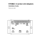
Section General Specifications 1-4 Repeater Units Model RPT01-P, RPT01 4 Function Used when more than 32 Optical Transmitting I/O Units, Slave Racks, etc., are connected in series. Supply voltage Operating voltage range Power consumption 100 to 120/200 to 240 VAC or 12 to 24 VAC/DC 85 to 264 VAC 8 VA max. Weight 600 g max.
SECTION 2 Wiring and Power Supply 2-1 2-2 2-3 2-4 2-5 2-6 Power Supply and Cable Lengths . . . . . . . . . . . . . . . . . . . . . . . . . . . . . . . . . . . . . . . . . . . . RS-422 and RS-232C Cable . . . . . . . . . . . . . . . . . . . . . . . . . . . . . . . . . . . . . . . . . . . . . . . . . Optical Fiber Cable (APF/PCF) . . . . . . . . . . . . . . . . . . . . . . . . . . . . . . . . . . . . . . . . . . . . . . Crystal Optical Fiber Cable (AGF) . . . . . . . . . . . . . . . . . . . . . . . . . . .
Section RS-422 and RS-232C Cable 2-1 2-2 Power Supply and Cable Lengths Power Supply For all but AL001 Link Adapters, connect the AC hot line to the common terminal of the Link Adapter. A fuse is internally connected to the common line. Cable Lengths Maximum length for RS-232C cable is 15 m. For RS-422 it is 500 m, with a maximum of 10 m for any given branch line. For RS-485 cable it is 200 m.
Section RS-422 and RS-232C Cable Connecting Link Adapter AL004-(P)E 2-2 When using a Link Adapter, connect both RS-232C and RS-422 cable straight across, as shown in the following diagram. Here the SD terminal of the host computer, for example, is connected to the SD terminal of the Link Adapter. See 5-4 Link Adapter AL004-(P)E for the internal configuration of the Link Adapter.
Section Optical Fiber Cable (APF/PCF) 2-3 Observe the following when soldering wires onto the connector. Soldering 1, 2, 3... Hood Assembly 1. Place heat-shrink tubing onto all wires far enough from the end so as to not interfere with soldering. 2. Pre-solder all wires and connector terminals. 3. Solder all wires, inserting 4 mm of the exposed 5 mm of wire into the connector terminal. 4. Slide the heat-shrink tubing onto the soldered area and shrink into place.
Section Crystal Optical Fiber Cable (AGF) 2-4 7. Do not allow heavy objects to fall on optical cable or otherwise subject it to excessive shock or strain.
Section Backup Power Supply 2-5 When total transmission loss from the system is subtracted from the transmit/receive differential of the Link Adapters, the margin must be at least 4 dB. To determine total transmission loss, first calculate the loss over the cable by multiplying the loss/km by the total length of the cable. Then calculate the loss at the connections by multiplying the loss/connection by the number of connections. Finally, add the cable loss and the connector loss.
Backup Power Supply Section 2-5 The following diagram illustrates a situation in which a 12V battery is used as a backup power supply, connected to the Link Adapter in Plant B. If there were no backup power supply in this case, then a power failure in Plant B would cut off signal transmission between Plant A and Plant C. By connecting the backup battery in Plant B this is avoided, and continued transmission is assured.
Section Link Adapter Repeater Input 2-6 2-6 Link Adapter Repeater Input Link Adapters AL002-(P)E and AL006-(P)E have repeater input terminals. They are used when it is necessary to be sure that power has already been turned on in a system connected to a branch line of the Link Adapter before signals are transmitted along the main line. They should be kept connected (ON) when not needed. When they are connected across, signals are relayed along the Link Adapter’s main line.
SECTION 3 Repeater Units 13
Section Repeater Units 3 Repeater Unit RPT01-(P) must be used when the number of Optical Slave Racks, Optical Transmitting I/O Units, I/O Link Units, and Link Adapters connected in series exceeds 32. Insert a Repeater Unit between the 32nd and 33rd Units. The example below shows an Optical Slave Rack and Optical Transmitting I/O Units connected in series. Note that a Repeater Unit is inserted after the total of these Units reaches 32.
Repeater Units Section 3 Connections Dimensions 15
SECTION 4 System Configuration Various system configurations call for the use of particular Link Adapters. This section presents a number of examples which illustrate the usage of Link Adapters in PC Link Systems, Host Link Systems, Optical Remote I/O Systems, and Wired Remote I/O Systems. See 1-4 General Specifications for details on the functions and specifications of particular Link Adapters. 4-1 4-2 4-3 4-4 PC Link Systems . . . . . . . . . . . . . . . . . . . . . . . . . . . . . . . . . . . . . . . .
Section PC Link Systems 4-1 4-1 PC Link Systems It is necessary to use Link Adapters when 3 or more PC Link Units are connected in a System. Example 1 A PC Link System can be connected using Link Adapter AL001 as shown in the diagram below. CPU Rack with PC Link Unit CPU Rack with PC Link Unit CPU Rack with PC Link Unit RS-422 branch line (10 m max.) RS-422 RS-422 branch line (10 m max.
Section Host Link Systems 4-2 4-2 Host Link Systems Link Adapters are used in Host Link Systems for branching and for converting to the type of cable required by the host computer. A Wired Host Link System can be connected using Link Adapters AL004-(P)E and AL001 as shown below. Link Adapter AL004-(P)E is used to convert between RS-232C and RS-422 cable. Link Adapter AL001 is used for branching. Example 1 Host computer RS-232C(15 m max.
Section Optical Remote I/O Systems Example 3 4-3 As shown in Example 3, more than one Optical Host Link Unit can be connected in series using optical fiber cables. However, if any failure (power failure, disconnection, etc.) occurs in one of the Units, all the subsequent Host Link Units will also cease to operate. This can be prevented by using Link Adapters such as the AL002-(P)E as shown below.
Section Optical Remote I/O Systems 4-3 An Optical System with Optical Transmitting I/O Units can be connected with crystal optical fiber cable (AGF) by using Link Adapter AL005-(P)E as shown below: Example 2 Link Adapter AL005-(P)E Link Adapter AL005-(P)E Crystal optical fiber (AGF) CPU Rack with Optical Master Optical Slave Rack Optical fiber (APF/PCF) Optical Transmitting I/O Units Example 3 An Optical System with an I/O Link Unit can be connected with crystal optical fiber cable by using Link
Section Wired Remote I/O Systems 4-4 4-4 Wired Remote I/O Systems Wired Remote I/O Master Units, Remote I/O Slave Units, and Remote Terminals can be directly connected with RS-485 cable, which has a maximum transmission distance of 200 m. In order to extend the transmission distance and/or to reduce noise interference, a pair of AL007-P Link Adapters can be used to insert an optical link between any two Remote I/O Units/Remote Terminals.
SECTION 5 Dimensions and Internal Configuration 5-1 5-2 5-3 5-4 5-5 5-6 Link Adapter AL001 . . . . . . . . . . . . . . . . . . . . . . . . . . . . . . . . . . . . . . . . . . . . . . . . . . . . . . Link Adapter AL002-(P)E . . . . . . . . . . . . . . . . . . . . . . . . . . . . . . . . . . . . . . . . . . . . . . . . . . Link Adapter AL004-(P)E . . . . . . . . . . . . . . . . . . . . . . . . . . . . . . . . . . . . . . . . . . . . . . . . . . Link Adapter AL005-(P)E . . . . . . . . . . . . . . . . . . . .
Section Link Adapter AL001 5-1 Link Adapter AL001 Note Unit of measurement: mm 24 5-1
Section Link Adapter AL002-(P)E 5-2 5-2 Link Adapter AL002-(P)E The Link Adapter can run on either 100/200 VAC or 12-24 VAC/DC. The repeater input terminals should be shorted across when not being used. For details on the usage of the repeater input, refer to 2-6 Link Adapter Repeater Input. For backup power supplies, see 2-5 Backup Power Supply.
Section Link Adapter AL004-(P)E 5-3 5-3 Link Adapter AL004-(P)E 0V External line Available (Yes) Not available (No) Terminating resistance selector switch Switch Settings CTS Selector Set to 0 V to have the clear-to-send (CTS) signal always ON. Set to external to receive an external CTS signal. Termination Resistance When set to ON, connects the built-in termination resistance (220 Ω); when set to OFF, disconnects it.
Section Link Adapter AL005-(P)E 5-4 5-4 Link Adapter AL005-(P)E Use FC connecters for AGF (crystal optical fiber;) cable. AGF connecters have fixed positions for reception and transmission, so be careful to connect them correctly. The Link Adapter can operate on either 100/200 VAC or 12-24 VAC/DC. For details on auxiliary power supplies, see 2-5 Backup Power Supply.
Section Link Adapter AL006-(P)E 5-5 5-5 Link Adapter AL006-(P)E Use FC connecters for AGF cable. AGF connecters have fixed positions for reception and transmission, so be careful to connect them correctly. This Link Adapter can operate on either 100/200 VAC or 12-24 VAC/DC. The repeater input terminals should be shorted across when not being used. For details on how to use the repeater input, see 2-6 Link Adapter Repeater Input. For details on auxiliary power supplies, see 2-5 Backup Power Supply.
Section Link Adapter AL007-P 5-6 5-6 Link Adapter AL007-P The AL007-P is used exclusively for Wired Remote I/O Systems. It cannot be used in Optical Remote I/O Systems, nor can it be used in combination with an AL002-(P)E.
Appendix A Standard Models Name Link Adapter Specifications Model Number Optical (APF/PCF) (3 connectors) 3G2A9-AL002-PE RS-422 (2 connectors), RS-232C (1 connector) 3G2A9-AL003-E Optical (APF/PCF), RS-422, RS-232C (1 conn.
Appendix A Standard Models Wire Cable We recommend the following cables for RS-422, RS-232C, and RS-485 connections. Cable type 32 Recommended Cable RS-232C CO-DS-IREVV-SX-10P x 0.18 mm2 (Hitachi Cable) RS-422 CO-HC-ESV-3P x 7/0.2 (Hirakawa Cable) RS-485 VCTF 0.
Index A application precautions, C cable connectors optical fiber cable, soldering, wire cable, wiring, CTS selector, H host computers, , connecting to, , Host Link Systems, , , , optical, wired, P PC Link Systems, , , , power interruption, backup power supply, , bypassing malfunctioning Unit, , power supply, specifications, , precautions, applications, general, operating environment, safety, R Remote I/O Master Units, , Remote I/O Slave Units, , Remote Terminals, repeater input, , , I Repeater Units,
Revision History A manual revision code appears as a suffix to the catalog number on the front cover of the manual. Cat. No. W123-E1-3 Revision code The following table outlines the changes made to the manual during each revision. Page numbers refer to previous version. Revision code 1 Date 1990 2 September 1990 Revised content Original production First production in Interleaf. Put into current manual format.
Authorized Distributor: Cat. No. W123-E1-3 Note: Specifications subject to change without notice.