
Datasheet

2
A6SRA6SR
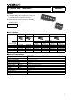
■Dimensions (Unit: mm)
Note: Unless otherwise specified, a tolerance of ±0.4 mm applies to all dimensions.
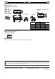
■Internal Connections
Contact Form (Top View)
■Precautions
Be sure to read the Safety precautions common to all DIP Switches for correct use.
6
5
0.6
0.8
A
±
0.2
1.22
0.1
2.54
20°
0.9
9.8
0.7 0.7
9.8
0.7 0.7
2.54 × (P-1)
P : Pole numbers
Long actuatorShort actuator
2.54 × (P-1)
±0.1
P: Number of poles
10.4
7.4
1.1
● Short actuator / Long actuator
A6SR-@101
A6SR-@101-P
A6SR-@101-R100
A6SR-@104
A6SR-@104-P
A6SR-@104-R100
No. of poles
Model
Dimension A
Short actuator Long actuator
2 A6SR-2101 A6SR-2104 4.98
4 A6SR-4101 A6SR-4104 10.06
6 A6SR-6101 A6SR-6104 15.14
8 A6SR-8101 A6SR-8104 20.22
10 A6SR-0101 A6SR-0104 25.30
Dimensions of PCB Pad (Reference)
(Top View)
1
ON
2910
• Application examples provided in this document are for reference only. In actual applications, confirm equipment functions and safety before using the product.
• Consult your OMRON representative before using the product under conditions which are not described in the manual or applying the product to nuclear control systems, railroad
systems, aviation systems, vehicles, combustion systems, medical equipment, amusement machines, safety equipment, and other systems or equipment that may have a serious
influence on lives and property if used improperly. Make sure that the ratings and performance characteristics of the product provide a margin of safety for the system or
equipment, and be sure to provide the system or equipment with double safety mechanisms.
Cat. No. A210-E1-04
0619(0207)(O)
Note: Do not use this document to operate the Unit.
OMRON Corporation
Electronic and Mechanical Components Company
Contact: www.omron.com/ecb