
User's Manual


21
RFID System
User's Manual
Section 2 㪥㪫㪣㪧㩷㪠㪛䉶 䊮䉰
Section 2
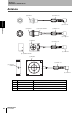
㪥㪸㫄㪼㫊㩷㪸㫅㪻㩷㪝㫌㫅㪺㫋㫀㫆㫅㫊㩷㫆㪽㩷㪚㫆㫄㫇㫆㫅㪼㫅㫋㫊
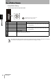
Mode Setting Switch
•Access Mode Setting
Set the opeation mode for communications with the ID Tag.
Mode setting switch setting are read only when the power supply is turned ON. Therefore, settings cannot be changed
while the power is being supplied. Turn the power supply OFF before changing the settings.
The position of the arrow in the figure is the
direction in which the setting is made.
No. Name Description
㪩㪼㫄㪸㫉㫂㫊
0 SYNC_MODE
1
Operates as Trigger Mode 1. Communications with the ID Tag will start with input.
1AUTO_MODE
1
Operates as Auto Mode 1. Once the power supply is turned ON, communications with the ID
Tag will start automatically when the ID Tag enters the communica-
tions range of the Antenna.
2 SYNC_MODE
2
Operates as Trigger Mode 2. The result output method is different for Trigger Modes 1 and 3.
For details, refer to Mode 2 in Section 5 I/O Interface Con-
trol.
p.75
3AUTO_MODE
2
Operates as Auto Mode 2. The result output method is different for Trigger Modes 1 and 3.
For details, refer to Mode 2 in Section 5 I/O Interface Con-
trol.
p.76
4 SYNC_MODE
3
Operates as Trigger Mode 3. The result output method is different for Trigger Modes 1 and 2.
For details, refer to Mode 3: Wire Saving in Section 5 I/O
Interface Control.
p.84
5AUTO_MODE
3
Operates as Auto Mode 3. The result output method is different for Auto Modes 1 and 2.
For details, refer to Mode 3: Wire Saving in Section 5 I/O
Interface Control.
p.74
6 NOISE
CHECK
Operates as Noise Measurement
Mode.
Maintenance mode for measuring environmental noise.
For details, refer to ntlp Noise Check in ntlp Section 5 I/O
Interface Control.
p.103
7 - Setting prohibited
(An access mode setting error will occur.)
8
9