
User Manual


Section 6 APPENDIX
Section 6
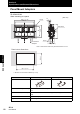
Specifications and External Dimensions
127
ZFV-C
User’s Manual
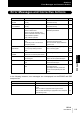
Input signals (1) Simultaneous measurement input (TRIG)/ Continuous measurement input
(TRIG) switched by menu.
(2) Bank selection inputs (BANK1-3)
(3) Workpiece still teaching (TEACH)/Workpiece moving teaching (TEACH)
Switched by menu
Sensor Head interface Digital interface
Image display 1.8-inch TFT color LCD (557 × 234 pix)
Indicators • Judgment result indicator (OUT, orange)
• Inspection mode indicator (RUN, green)
• Error indicator (ERR, red)
• READY indicator (READY, blue)
Operation interface • Cursor keys (up, down, left, right) • Setting key (SET)
• Escape key (ESC)
• Operating mode switching (slide switch) • Menu switching (slide switch)
• Teaching/Display switching key (TEACH/VIEW)
• Function keys (A to D 4 input)
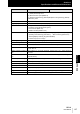
Power supply voltage 20.4 to 26.4 VDC (including ripple)
Current consumption 800 mA max. (with Sensor Head connected)
Dielectric strength 1,000 VAC, 50/60 Hz for 1 min between leads and Amplifier Unit case
Noise Resistance 1 kV, Pulse rise: 5 ns, Pulse width: 50 ns, Burst duration: 15 ms
Cycle: 300 ms
Vibration resistance (destruc-
tive)
10 to 150 Hz, 0.1 mm single amplitude, 10 times each in X, Y, and Z directions
for 8 min
Shock resistance (destruc-
tive)
Destruction: 150 m/s
2
, three times each in six directions (up/down, left/right, for-
ward/backward)
Ambient temperature range Operating: 0 to +50 °C, Storage: -25 to +65 °C (with no icing or condensation)
Ambient humidity range Operating and storage: 35 % to 85 %
Ambient atmosphere Must be free of corrosive gas.
Degree of protection IEC60529 IP20
Material Polycarbonate (PC)
Weight Approx. 300 g (including cord) (when packaged: approx. 450 g)
Accessories Ferrite core (1), Instruction sheet, Label (1)
Item ZFV-CA40 ZFV-CA45