
User Manual


Section 2 INSTALLATION & CONNECTION
Section 2
Amplifier Unit
39
ZFV-C
User’s Manual
About the I/O Cable
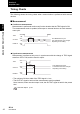
The following shows the leads that comprise the I/O cable.
(1) Power Supply
This connects the power supply.
Use a DC power supply with safe extra-low-voltage circuits to prevent high voltage.
Recommended power supply unit p.21
Wire the power supply separately from other devices. Wiring them together or placing
them in the same duct may cause induction, resulting in malfunction or damage.
(2) GND
The GND terminal is the 0 V power supply terminal.
(3) OUTPUT (control output)
This outputs judgment results. This lead is interlocked with OUTPUT LED.
(4) ENABLE (enable output)
This turns ON when the sensor is ready for measurement.
(5) ERROR (error output)
This turns ON when an error is generated. This lead is interlocked with ERR LED.
Error Messages and Corrective Actions p.119
(1) Power supply
(3) OUTPUT*1
(4) ENABLE
(5) ERROR
(6) TEACH*1
(7) TRIG*1
(8) BANK1*1
(9) BANK2*1
(10) BANK3*1
(2) GND
Brown
Blue
Black
Orange
Light blue
Yellow
Pink
Gray
Green
Red
*1: Enabled only in the RUN mode
Purple
White
Unused
Unused