
Datasheet
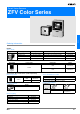
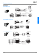
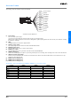

ZFV
C-9ZFV
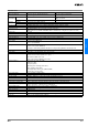
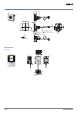
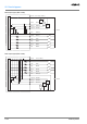
About the I/O cable
The following shows the leads that comprise the I/O cable.
(1) Power Supply
This connects the power supply.
Use a DC power supply with safe extra-low-voltage circuits to prevent high voltage.
Wire the power supply separately from other devices. Wiring them together or placing them in the same duct may cause induction, resulting
in malfunction or damage.
(2) GND
The GND terminal is the 0 V power supply terminal.
(3) OUTPUT (control output)
This outputs judgment results. This lead is interlocked with OUTPUT LED.
(4) ENABLE (enable output)
This turns ON when the sensor is ready for measurement.
(5) ERROR (error output)
This turns ON when an error is generated. This lead is interlocked with ERR LED.
(6) TEACH (teching input)
There are two teaching modes, workpiece stop teaching and workpiece move teaching. These teaching modes can be selected in the menu.
(7) TRIG (measurement trigger input)
There are two measurement modes, synchronus measurement and continuos measurement. Which mode of measurement is to be per-
formed in is selected in the menu.
(8) BANK1 (bank swichting input 1)
(9) BANK2 (bank swichting input 2)
(10) BANK3 (bank swichting input 3)
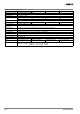
The bank No. can be switched when the BANK1 to BANK3 are connected as follows
.
Bank No. BANK1 BANK2 BANK3
BANK1 OFF OFF OFF
BANK2 ON OFF OFF
BANK3 OFF ON OFF
BANK4ONONOFF
BANK5 OFF OFF ON
BANK6 ON OFF ON
BANK7 OFF ON ON
BANK8ONONON
(1) Power supply
(3) OUTPUT*
(4) ENABLE
(5) ERROR
(6) TEACH*
(7) TRIG*
(8) BANK1*
(9) BANK2*
(10) BANK3*
(2) GND
Brown
Blue
Black
Orange
Light blue
Yellow
Pink
Gray
Green
Red
* : Enabled only in the RUN mode
Purple
White
Unused
Unused