
Datasheet


Smart Sensors (with Ultra-High-Speed CCD Camera) ZFV Series 5
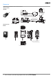
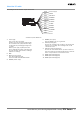
About the I/O cable
The following shows the leads that comprise the I/O cable.
1. Power supply
This connects the power supply.
Supply power from a DC power supply unit that
has a countermeasure (safety ultra-low voltage
circuit) built-in for preventing high voltages from
occurring.
Wire the power supply separately from other
devices. Wiring them together or placing them in
the same duct may cause induction, resulting in
malfunction or damage.
2. GND
3. OUTPUT (control output)
This outputs judgment results.
This lead is interlocked with OUTPUT LED.
4. ENABLE (enable output)
5. ERROR (error output)
This turns ON when an error is generated.
6. TEACH (teaching input)
There are two teaching modes, workpiece stop teaching and
workpiece move teaching. These teaching modes can be
selected in the menu.
7. TRIG (measurement trigger input)
There are two measurement modes, synchronous measure-
ment and continuous measurement. Which mode of measure-
ment is to be performed in is selected in the menu.
8. BANK1 (bank switching input 1)
9. BANK2 (bank switching input 2)
10. BANK3 (bank switching input 3)
(1) Power supply
(3) OUTPUT*
(4) ENABLE
(5) ERROR
(6) TEACH*
(7) TRIG*
(8) BANK1*
(9) BANK2*
(10) BANK3*
(2) GND
Brown
Blue
Black
Orange
Light blue
Yellow
Pink
Gray
Green
Red
* : Enabled only in the RUN mode
Purple
White
Unused
Unused