
Datasheet


Smart Sensors (with Ultra-High-Speed CCD Camera) ZFV Series 3
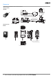
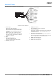
Amplifier Units
Note 1. This is the sampling rate when logging images. To log measurement data only, use the ZS-DSU settings.
2. Image logging is not possible when the ZS-MDC is connected.
Item Single-function models Standard models
ZFV-A10 ZFV-A15 ZFV-A20 ZFV-A25
Output method NPN PNP NPN PNP
Inspection items Pattern (PTRN), Brightness (BRGT) Patterns (PTRN), Brightness (BRGT), Area (AREA), Width
(WID), Position (POSI), Count (CNT), Characters (CHAR)
Teaching area Rectangular, one area
Teaching area size • Pattern (PTRN), Brightness (BRGT): Any rectangular area (256 × 256 max.)
• Area (AREA), Width (WID), Position (POSI), Count (CNT), Characters (CHAR): Any rectangular area (full screen max.)
Sensing area Full screen
Resolution 468 × 432 (H × V) max.
Bank selection Supported for 8 banks.
Response time Pattern (PTRN), Brightness (BRGT): High-speed: 4 ms, Standard: 8 ms, High-precision: 12 ms
Area (AREA), Width (WID), Position (POSI), Count (CNT), Characters (CHAR): 128 × 128: 15 ms max.
Other functions Control output switching: ON for OK or ON for NG
ON delay/OFF delay, One-shot output, “ECO” mode
Output signals (1) Control output (OUTPUT), (2) Enable output (ENABLE), (3) Error output (ERROR)
Input signals (1) Simultaneous measurement input (TRIG) or Continuous measurement input (TRIG), Switched by using menu.
(2) Bank selection inputs (BANK1 to BANK3)
(3) Workpiece still teaching (TEACH) or Workpiece moving teaching (TEACH), Switched by using menu.
Con-
necting
to ZS-
DSU
Image
logging
trigger
Stores NG images or all images.
Sampling
rate
ZFV measurement cycle (See note 1.)
Number of
logged
image
Logs up to 128 images in series
Number of
connected
15 max. (ZFV: 5 Units max., ZS-LDC: 9 Units max., ZS-MDC (See note 2.): 1 Unit max.)
External
bank
function
Amplifier Unit setting data can be saved to the memory card as bank data. Reading bank data enables bank switching.
Sensor Head
interface
Digital interface
Image display Compact TFT 1.8-inch LCD (Display dots: 557 × 234)
Indicators • Judgement result indicator (OUTPUT) • Inspection mode indicator (RUN)
Operation interface • Cursor keys (up, down, left, right) • Setting key (SET) • Escape key (ESC)
• Operating mode switching (slide switch) • Menu switching (slide switch)
• Teaching/Display switching key (TEACH/VIEW)
Power supply voltage
20.4 to 26.4 VDC (including ripple)
Current consumption
600 mA max. (with Sensor Head connected)
Dielectric strength
1,000 VAC, 50/60 Hz for 1 min between leads and Amplifier Unit case
Noise immunity
1 kV, Pulse rise: 5 ns, Pulse width: 50 ns, Burst duration: 15 ms, Cycle: 300 ms
Vibration resistance
Destruction: 10 to 150 Hz, 0.1-mm single amplitude, 10 times each in X, Y, and Z directions for 8 min
Shock resistance
Destruction: 150 m/s
2
, three times each in six directions (up/down, left/right, forward/backward)
Ambient temperature
Operating: 0 to 50°C
Storage: −25 to 65°C (with no icing or condensation)
Ambient humidity
Operating and storage: 35% to 85%
Ambient atmosphere
Must be free of corrosive gas.
Degree of protection
IEC60529, IP20
Materials
Polycarbonate
Weight
Approx. 300 g (including cord)
Accessories
Ferrite core (1), Instruction sheet