
Datasheet

8
ZE/ZV/ZV2/XE/XV/XV2
Note: Unless otherwise specified, a tolerance of ±0.4 mm applies to all dimensions.
Safety Precautions
Refer to Safety Precautions for All Limit Switches.
Operating Environment
• Seal material may deteriorate if a Switch is used outdoor or where
subject to special cutting oils, solvents, or chemicals. Always
appraise performance under actual application conditions and set
suitable maintenance and replacement periods.
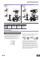
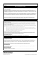
• Be sure to protect part A with grease in order to maintain the
mechanical durability and performance of the Limit Switch. The use
of molybdenum disulfide grease is recommended.
• Install Switches where they will not be directly subject to cutting
chips, dust, or dirt. The Actuator and Switch must also be protected
from the accumulation of cutting chips or sludge.
• Constantly subjecting a Switch to vibration or shock can result in
wear, which can lead to contact interference with contacts,
operation failure, reduced durability, and other problems.
Excessive vibration or shock can lead to false contact operation or
damage. Install Switches in locations not subject to shock and
vibration and in orientations that will not produce resonance.
• The Switches have physical contacts. Using them in environments
containing silicon gas will result in the formation of silicon oxide
(SiO
2) due to arc energy. If silicon oxide accumulates on the
contacts, contact interference can occur. If silicon oil, silicon filling
agents, silicon cables, or other silicon products are present near the
Switch, suppress arcing with contact protective circuits (surge
killers) or remove the source of silicon gas.
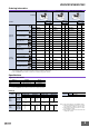
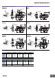
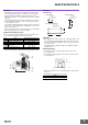
ZV-NA2-2
ZV2-NA2-2
XV-NA2-2
XV2-NA2-2
ZV-NA277-2
ZV2-NA277-2
XV-NA277-2
XV2-NA277-2
OF max.
RF min.
PT max.
OT min.
MD max.
6.28 N
2.26 N
5 mm
6 mm
0.4 mm
7.26 N
2.26 N
6 mm
5.5 mm
0.72 mm
6.28 N
2.26 N
5 mm
6 mm
0.4 mm
7.26 N
2.26 N
6 mm
5.5 mm
0.72 mm
Precautions for Correct Use
23
*3
*1
17
79
±0.8
39.5
±0.8
39.7
*2
5441.3±0.2
53R
36.6
10.6
±0.3
86
75
±0.2
5.5
19.3
(23.1)
25.4
±0.3
3
PT
31
±0.2
5
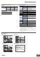
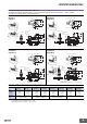
*1. Stainless sintered alloy roller
*2. Adjustment between 0° to 225°.
*3. Only the ZV2-NA2-2 and XV2-NA2-2 incorporate mounting holes.
JIS B0202
G1/2
Effective
thread: 4
threads min.
t=3 (ZV-NA2-2/XV-NA2-2 flanges)
+0.2
0
Two, 5.4 dia.
holes
Two, 4.3±0.2 dia.
19.1 dia.
× 9
Sealed Roller Arm Lever
ZV(2)-NA2-2
XV(2)-NA2-2
54
53R
36.6
23
17
39.7
*2
17.4R
86
5.5
5
19.3
(40)
3
PT
*3
*1
79±0.8
39.5
±0.8
41.3
±0.2
10.6
±0.3
25.4
±0.3
31
±0.2
75
±0.2
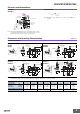
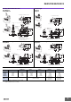
*1. Stainless steel roller
*2. Adjustment between 0° to 225°.
*3. Only the ZV2-NA277-2 and XV2-NA277-2 incorporate
mounting holes.
JIS B0202
G1/2
Effective
thread: 4
threads min.
t=3 (ZV-NA277-2/XV-NA277-2 flanges)
18.7 dia. × 9
Operates in this
direction only
Two, 4.3±0.2 dia. holes
+0.2
0
Two, 5.4 dia.
holes
One-way Action Sealed Roller Arm Lever
ZV(2)-NA277-2
XV(2)-NA277-2
Not Suitable Suitable