
Datasheet

XS3
20
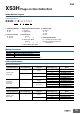
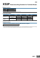
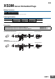
XS3M Panel-mounting Plugs
Mating Connectors
Ordering Information
Note: Orders are accepted in multiples of the minimum order.
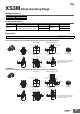
Dimensions (Unit: mm)
Item Model
XS3M-M524-1@ XS3F-M52@-5@@-A
Lock method Pin shape Shield pin Applicable wires Model
Front lock
DIP pins 4.5 mm
(for either round holes or solder cups)
No
AWG26 max.
XS3M-M524-10
Yes XS3M-M524-11
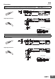
● Front lock DIP pins (5 pins)
XS3M-M524-@@
XS3M-M524-10
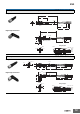
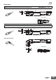
Front Lock with DIP Pins 4.5 mm (for Either Round Holes or Solder Cups), Without Shield Pin
XS3M-M524-11
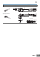
Front Lock with DIP Pins 4.5 mm (for Either Round Holes or Solder Cups), With Shield Pin
SW10
SW7
1.95
3.4
7.05
(2.5)
6 min.
12
5-4.5
Panel location (example for t = 2.0)
8.2 mm dia.
+0.1
0
7.1
+0.1
0
11.9 dia.
SW11
1.95
3.4
1.45
1.35
0.35
Five, 1.7 dia. lands
Five, 1.2 dia.
1
2
3
4
5
Pin Numbers
0.35
1.35
1.45
2-1.45
1.35
3.4
1.95
2-0.35
5-1 dia.
O-ring on panel side*
O-ring on panel side*
M8 × 1.0
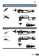
Panel Cutout PCB-mounting Dimensions
Panel Cutout PCB-mounting Dimensions
SW10
SW7
1.95
O-ring on panel side*
O-ring on panel side*
3.4
7.05
2-4.5
(2.5)
6 min.
12
5-4.5
Panel location (example for t = 2.0)
10.4
11.9 dia.
SW11
1.95
3.4
1.45
1.35
0.35
Five, 1.7 dia. lands
Five, 1.2 dia.
4-R0.6
4-R0.35
Two, 1.2 lands
Two, 3.8
lands
Two, 3.3
lands
2-0.7
1
2
3
4
5
Pin Numbers
0.35
1.35
1.45
2-1.45
1.35
3.4
1.95
10.4
2-0.35
5-1 dia.
2-2.6
8.2 mm dia.
+0.1
0
7.1
+0.1
0
M8 × 1.0
*The O-ring on the panel side maintains
a waterproof structure (IP67) between
the panel and Connector.
*The O-ring on the panel side maintains
a waterproof structure (IP67) between
the panel and Connector.
Note: The panel thickness is
0.8 to 2 mm.
Note: The panel thickness is 2.4 mm
maximum.
Note: The panel thickness is
0.8 to 2 mm.
Note: The panel thickness is 2.4 mm
maximum.