
Datasheet

10 Switch Mode Power Supply S8VM
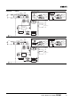
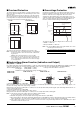
■ Probable Causes of Power Supply Errors and Troubleshooting Using
Undervoltage Alarm Function
Check the following information if the Undervoltage Alarm Function operates.
Contact your OMRON representative if the Power Supply does not function normally after checking.
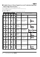
The symbols in the table are as follows:
: Lit, : Not lit, : Flashing
Note: Flashing: The output voltage is unstable, causing the LED to repeatedly turn ON and OFF.
DC ON DC LOW1 DC LOW2
Output voltage Power Supply status diagnosis
LED D:
Green
LED F:
Yellow
Transistor
outputs
(H to J)
LED G:
Red
Transistor
outputs
(I to J)
1ONON→
Normal
(approx. 90% min.
of rated output
voltage)
Normal status
2OFFON
→
Normal
(approx. 90% min.
of rated output
voltage)
The output voltage has re-
covered to normal status
following a previous sud-
den voltage drop.
3ONOFF
→
Output drop
(approx. 90%
max. of rated
output voltage)
The output voltage has
dropped gradually and re-
mains low.
4OFFOFF
→
Output drop
(approx. 90%
max. of rated
output voltage)
The output voltage re-
mains low following a pre-
vious sudden voltage
drop.
5OFF
ON
OFF
→
Output drop
(approx. 80% of
rated output
voltage)
The output voltage re-
mains low and is continu-
ing to fluctuate following a
previous sudden voltage
drop.
6ON
ON
OFF
→
Output drop
(approx. 80% of
rated output
voltage)
The output voltage has
dropped gradually, re-
mains low, and is continu-
ing to fluctuate.
7OFFOFF
→ No output
No output voltage is being
output.
8
ON
OFF
ON
OFF
→ Unstable output
The output voltage is un-
stable.
24 V
24 V
24 V 24 V
⇔
24 V
⇔
24 V
⇔
⇔
24 V