
Datasheet
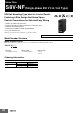

S8V-NF
30
Engineering Data
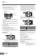
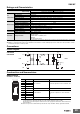
Derating Curves
S8V-NFS203 S8V-NFS206
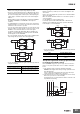
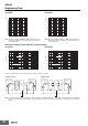
Attenuation Frequency Characteristics (Typical example)
S8V-NFS203 S8V-NFS206
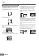
The above characteristics are data acquired by the following measurement circuits.
Note: The noise filter attenuation characteristics are measured under a constant I/O impedance of 50 Ω. When used attached to actual equipment,
the power line impedance varies depending on the wiring method. Therefore, attenuation characteristics may not match those listed in the
catalog.
Note: If using at an altitude of 2000 m to 3000 m, multiply the above
derating curve by 0.8 to reduce the load. (Does not apply for
face-up mounting)
0
20
40
60
80
100
120
-40 -30 -20 -10 0 10 20 30 40 50 60 70 80 90
Load ratio (%)
Operating temperature (°C)
Note: If using at an altitude of 2000 m to 3000 m, multiply the above
derating curve by 0.8 to reduce the load. (Does not apply for
face-up mounting)
50%
0
20
40
60
80
100
120
-40 -30 -20 -10 0 10 20 30 40 50 60 70 80 90
Load ratio (%)
Operating temperature (°C)
Frequency (MHz)
Attenuation (dB)
0.1
10
20
30
40
50
60
70
80
90
100
Common mode
0
1 10 100
Normal mode
0.1
10
20
30
40
50
60
70
80
90
100
Common mode
Normal mode
0
1 10 100
Frequency (MHz)
Attenuation (dB)
Common mode Normal mode
SG
SG
Signal generator Measuring device Signal generator Measuring device
50 Ω
50 Ω
50 Ω
50 Ω 50 Ω
Power distributor
S8V-NF
Balun
S8V-NF
Balun