
Datasheet

S8VK-X
15
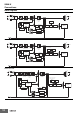
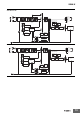
*1. The fuse is located on the (L) side. For a DC input, connect the positive voltage to the L terminal.
*2. This is the protective earth terminal specified in the safety standards. Always ground this terminal.
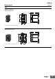
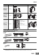
No.
Terminal
name
Name Function
1 L1
Input terminals Connect the input lines to these terminals. * 1
2 L2
3 N1
4 N2
5 PE
Protective Earth terminal (PE)
Connect the ground line to this terminal. * 2
6 +V1
DC Output terminals Connect the load lines to these terminals.
7 +V2
8 -V1
9 -V2
10 -V3
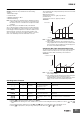
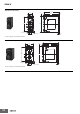
11 --- Output indicator (DC ON: Green) The green indicator indicates when a DC voltage is being output.
12 --- Alarm indicator (ALM: Red)
Lights up in red when a Power Supply abnormality occurs.
Refer to Self-Diagnostics Function on page 11 for details.
13 --- Output voltage adjuster (V. ADJ) Use to adjust the output voltage.
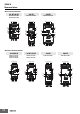
14 --- Main display (white) Displays measured values.
15
---
Operation indicator
(white)
V Lights up when the output voltage is indicated.
--- A Lights up during indication of output current.
--- Apk Lights up during indication of peak hold current.
--- Yrs Lights up during replacement time calculation year indication.
--- % Lights up during years until replacement time indication.
--- kh Lights up during percentage until replacement time indication.
16 ---
Indication switching/reset key (types with indication
monitor)
Reset key (types without indication monitor)
Used to change the indicated parameter.
Used to reset the peak hold current or communication settings.
For reset methods, refer to Communication Reset Function on page 9.
17 --- EtherNet/IP port Connects to EtherNet cables.
18 --- Module status indicator (MS)
Refer to Module Status and Network Status Indicators on page 9 for details.
19 --- Network status indicator (NS)