
Datasheet


S8VK-G
18
Wiring
Connect the ground completely. A protective earthing terminal
stipulated in safety standards is used. Electric shock or malfunction
may occur if the ground is not connected completely.
Minor fire may possibly occur. Ensure that input and output
terminals are wired correctly.
Do not apply more than 75-N force to the terminal block when
tightening it.
Be sure to remove the sheet covering the Product for machining
before power-ON so that it does not interfere with heat dissipation.
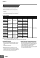
Use the following material for the wires to be connected to the
S8VK-G to prevent smoking or ignition caused by abnormal loads.
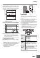
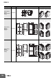
Terminals and Wiring
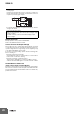
Strip I/O wires for 8 mm when using a screwless terminal block.
Note: The rated current for output terminals is 10 A per terminal.
Be sure to use multiple terminals simultaneously for current that exceeds the terminal rating.
When applying a current of 10 A or more, use at least two terminals each for the positive and negative wires.
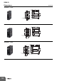
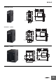
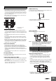
Installation Environment
Do not use the Power Supply in locations subject to shocks or
vibrations. In particular, install the Power Supply as far away as
possible from contactors or other devices that are a vibration
source.
Install the Power Supply well away from any sources of strong,
high-frequency noise and surge.
Operating Life
The life of a Power Supply is determined by the life of the
electrolytic capacitors used inside. Here, Arrhenius Law applies,
i.e., the life will be cut in half for each rise of 10C or the life will be
doubled for each drop of 10C. The life of the Power Supply can
thus be increased by reducing its internal temperature.
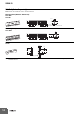
Ambient Operating and Storage Environments
Store the Power Supply at a temperature of 40 to 85C and a
humidity of 0% to 95%.
Do not use the Power Supply in areas outside the derating curve
otherwise, internal parts may occasionally deteriorate or be
damaged.
Use the Power Supply at a humidity of 0% to 95%.
Do not use the Power Supply in locations subject to direct sunlight.
Do not use locations where liquids, foreign matter, or corrosive
gases may enter the interior of Products.
Precautions for Safe Use
INPUT OUTPUT PE
Model
American
Wire Gauge
Solid Wire
/Stranded Wire
American
Wire Gauge
Solid Wire
/Stranded Wire
American
Wire Gauge
Solid Wire
/Stranded Wire
S8VK-G01505
AWG24 to 12
0.25 to 4 mm
2
/0.25 to 2.5 mm
2
AWG20 to 12
0.5 to 4 mm
2
/0.5 to 2.5 mm
2
AWG14 or thicker
2.5 mm
2
or thicker
/2.5 mm
2
or thicker
S8VK-G01512 AWG22 to 12
0.35 to 4 mm
2
/0.35 to 2.5 mm
2
S8VK-G01524 AWG24 to 12
0.25 to 4 mm
2
/0.25 to 2.5 mm
2
S8VK-G03005
AWG24 to 12
0.25 to 4 mm
2
/0.25 to 2.5 mm
2
AWG18 to 12
0.75 to 4 mm
2
/0.75 to 2.5 mm
2
S8VK-G03012 AWG20 to 12
0.5 to 4 mm
2
/0.5 to 2.5 mm
2
S8VK-G03024 AWG22 to 12
0.35 to 4 mm
2
/0.35 to 2.5 mm
2
S8VK-G06012
AWG22 to 12
0.35 to 4 mm
2
/0.35 to 2.5 mm
2
AWG18 to 12
0.75 to 4 mm
2
/0.75 to 2.5 mm
2
S8VK-G06024 AWG20 to 12
0.5 to 4 mm
2
/0.5 to 2.5 mm
2
S8VK-G12024 AWG22 to 10
0.35 to 6 mm
2
/0.35 to 4 mm
2
AWG18 to 10
0.75 to 6 mm
2
/0.75 to 4 mm
2
S8VK-G24024
AWG20 to 10
0.5 to 6 mm
2
/0.5 to 4 mm
2
AWG14 to 10
2.5 to 6 mm
2
/2.5 to 4 mm
2
S8VK-G24048 AWG18 to 10
0.75 to 6 mm
2
/0.75 to 4 mm
2
S8VK-G48024
AWG16 to 10
1.5 to 6 mm
2
/1.5 to 4 mm
2
AWG12 to 10
4 to 6 mm
2
/4 mm
2
S8VK-G48048 AWG14 to 10
2.5 to 6 mm
2
/2.5 to 4 mm
2