
Datasheet
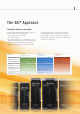

S8VK
Series line-up
11
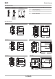
S8VK-G Nomenclature
S8VK-G Dimensions
12
5
4
3
321
5
4
12
4
5
3
S8VK-G030@@
S8VK-G12024
S8VK-G240@@
S8VK-G015@@ S8VK-G060@@ S8VK-G480@@
No. Name Function
1 AC Input terminals, (L) & (N)
The fuse is located on the L side.
2 PE (Protective earthing) Terminal.
PE terminal stipulated in the safety standards is used. Connect fully to ground.
3 DC output terminal (+V) + (–V)
4 Output Indicatior (DC ON: Green)
5 Output Voltage Adjuster (V.ADJ)
3.5
1
22.5
4.7
(Sliding: 10 max.)
Rail Stopper
91
5
75.4
90
S8VK-G015@@
40
125
4.7
(Sliding: 7.5 max.)
104.6
6.35
114
1
122.2
Rail Stopper
S8VK-G12024
4.7
(Sliding: 10 max.)
91
3.5
1
75.4
90
32
5
Rail Stopper
S8VK-G030@@
6.35
125
4.7
(Sliding: 7.5 max.)
60
104.6
141.8
1
151
Rail Stopper
S8VK-G240@@
90
32
5
75.4
4.7
(Sliding: 10 max.)
111
3.5
1
Rail Stopper
S8VK-G060@@
125
4.7
(Sliding: 7.5 max.)
6.35
52.3
Rail Stopper
151
140.8
1
95
S8VK-G480@@
S8VK
Series line-up
10
Specifications
S8VK-G Series
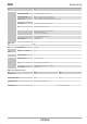
Power Boost Function
• Do not allow the boost current to continue for more than 10 seconds. Also, do not
let the duty cycle exceed the following conditions. These conditions may damage
Power supply.
• Ensure that the average current of one cycle of the boost current does not exceed
the rated output current. This may damage Power Supply.
• Lessen the load of the boost load current by adjusting the ambient temperature
and the mounting orientation.
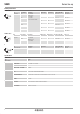
Derating Curve (As a reference)
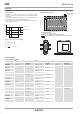
Terminals and Wiring
S8VK-G(15/30/60/120/240/480W)
* Wires to be stripped: 8 mm
[A]
t2
t1
I
p
: Boost current
l
ave
: Average current
output current
Defined condition for Power Boost availability.
t1 10 s
I
p
Rated boost current
l
ave
Rated current
Duty= × 100 [%] 30%
t1 + t2
t1
Ambient Temperature [˚C]
120
100
80
60
40
20
0
Load ratio [%]
Standard Installation
Face-up Installation
–40 –20 0 20 40 60 80
For Standard installation.
– 25 to 60˚C (-13 to 140˚F) at 100% load
Derating – 2.5% of load/K from 60 to 70˚C (from 140 to 158˚F)
The range that some parts of specifications are changed from Datasheet.
Top
Standard installation
Top
Face-up installation
INPUT OUTPUT PE
Model American Wire Gauge Solid Wire
/Stranded Wire
American Wire Gauge Solid Wire
/Stranded Wire
American Wire Gauge Solid Wire
/Stranded Wire
S8VK-G01505 AWG24 to 12 0.25 to 4 mm
2
/0.25 to 2.5 mm
2
AWG20 to 12 0.5 to 4 mm
2
AWG14 to 12 2.5 mm
2
to 4 mm
2
/2.5 mm
2
4 mm
2
/0.5 to 2.5 mm
2
S8VK-G01512 AWG22 to 12 0.35 to 4 mm
2
/0.35 to 2.5 mm
2
S8VK-G01524 AWG24 to 12 0.25 to 4 mm
2
/0.25 to 2.5 mm
2
S8VK-G03005 AWG24 to 12 0.25 to 4 mm
2
/0.25 to 2.5 mm
2
AWG18 to 12 0.75 to 4 mm
2
/0.75 to 2.5 mm
2
S8VK-G03012 AWG20 to 12 0.5 to 4 mm
2
/0.5 to 2.5 mm
2
S8VK-G03024 AWG22 to 12 0.35 to 4 mm
2
/0.35 to 2.5 mm
2
S8VK-G06012 AWG22 to 12 0.35 to 4 mm
2
/0.35 to 2.5 mm
2
AWG18 to 12 0.75 to 4 mm
2
/0.75 to 2.5 mm
2
S8VK-G06024 AWG20 to 12 0.5 to 4 mm
2
/0.5 to 2.5 mm
2
S8VK-G12024 AWG22 to 10 0.35 to 6 mm
2
/0.35 to 4 mm
2
AWG18 to 10 0.75 to 6 mm
2
AWG14 to 10 2.5 mm
2
to 6 mm
2
/2.5 mm
2
4 mm
2
/0.75 to 4 mm
2
S8VK-G24024 AWG20 to 10 0.5 to 6 mm
2
/0.5 to 4 mm
2
AWG14 to 10 2.5 to 6 mm
2
/2.5 to 4 mm
2
S8VK-G24048 AWG18 to 10 0.75 to 6 mm
2
/0.75 to 4 mm
2
S8VK-G48024 AWG16 to 10 1.5 to 6 mm
2
/1.5 to 4 mm
2
AWG12 to 10 4 to 6 mm
2
/4 mm
2
S8VK-G48048 AWG14 to 10 2.5 to 6 mm
2
/2.5 to 4 mm
2