
Datasheet
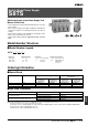

Switch Mode Power Supply S8TS L-29
Power
Supplies
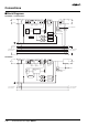
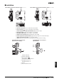
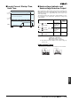
■ Installation
A AC Input Terminal (L): Connect an input line to this terminal.
B AC Input Terminal (N): Connect an input line to this terminal.
C Ground Terminal ( ): Connect a ground line to this terminal.
D Undervoltage Detection Output (DC LOW OUT): Open Collector output
E DC Output Terminal (–V): Connect load lines to this terminal.
F DC Output Terminal (+V): Connect load lines to this terminal.
G Output Indicator (DC ON: Green): Lights while DC output is ON.
H Undervoltage Indicator (DC LOW: Red): Lights when the voltage at the output terminal drops.
I Output Voltage Adjuster (V.ADJ): Use to adjust the voltage.
J Slider: Slide to the lock side when connecting. Unlock the slider when disconnecting.
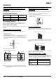
A AC Input Terminal (L)
B AC Input Terminal (N)
C Ground Terminal ( )
D Parallel Operation Signal Terminal
E DC Output Terminal (+V)
F DC Output Terminal (−V)
G Selector
H Projected Indicator Section
1
7
8
9
4 5 6
2 3
DC ON
DC LOW
DC LOW
V.ADJ
+V
-V
L
LN
N
50/60Hz
AC100
-240V
Class2
Power
Supply
DC24V
2.5A
INPUT
OUTPUT
1.0A
S8TS-06024
POWER SUPPLY
+V-V
10
10
4 5 6
1 2 3
7
8
9
DC ON
DC LOW
DC LOW
V.ADJ
+V
-
V
L
LN
N
50/60Hz
AC100
-240V
Class2
Power
Supply
DC24V
2.5A
INPUT
OUTPUT
1.0A
S8TS-06024F
POWER SUPPLY
+V-V
10
10
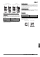
Basic Blocks with Screw Terminals: S8TS-@@@@@ Basic Blocks with Connector Terminals: S8TS-@@@@@F
1
8
2
7
3
4
5
6
1
2
3
8
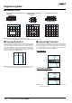
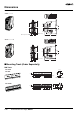
S8T-BUS01 Bus Line Connector
(AC Line + DC Line Bus)
S8T-BUS02 Bus Line Connector
(AC Line Bus)