
Datasheet

Switch Mode Power Supply S8TS L-27
Power
Supplies
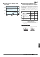
5-V Models (Basic Block: S8TS-02505@)
Note 1. If set to less than −10%, the undervoltage detection function may operate. Ensure that the output capacity and output current after adjust-
ment do not exceed the rated output capacity and rated output current respectively.
2. The output current is specified at power output terminals.
3. Refer to the explanations of functions on page 28 for details.
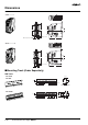
4. Be sure to mount End Plates (PFP-M) on both ends of the Power Supply.
■ Reference Value
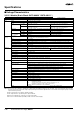
Item Single operation
Efficiency (typical) 62% min. (with rated input, 100% load)
Input Voltage 100 to 240 VAC (85 to 264 VAC)
Frequency 50/60 Hz (47 to 63 Hz)
Current 100 V input 0.7 A max.
200 V input 0.4 A max.
Power factor 0.8 min. (with rated input, 100% load)
Leakage current 100 V input 0.35 mA max.
240 V input 0.7 mA max.
Inrush current
(25°C, cold start)
(See note 2.)
100 V input 25 A max.
200 V input 50 A max.
Output (See
note 2.)
Voltage adjustment range 5 V ± 10% (with V. ADJ) (See note 1.)
Ripple 2% (p-p) max.
Input variation influence 0.5% max. (with 85 to 264 VAC input, 100% load)
Temperature variation influence 0.05%/°C max. (with rated input and output)
Load variation influence 1.5% max. (with rated input, 10% to 100% load)
Startup time (See note 3.) 1,000 ms max.
Hold time (See note 3.) 20 ms min. (with 100/200 VAC, rated input)
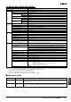
Additional
functions
Overcurrent protection (See note 3.) 105% to 125% of rated load current, inverted L drop type, automatic reset
Overvoltage protection (See note 3.) Yes
Parallel operation No
N+1 redundant system No
Series operation Yes (with the external diode)
Undervoltage indicator (See note 3.) Yes (color: red)
Undervoltage detection output (See note
3.)
Yes (open collector output), 30 VDC max., 50 mA max.
Other Ambient operating temperature (See note
3.)
Operating: Refer to the derating curve in Engineering Data.
Storage: −25 to 65°C (with no icing or condensation)
Ambient humidity Operating: 25% to 85%, Storage: 25% to 90%
Dielectric strength 3.0 kVAC, 50/60 Hz for 1 minute (between all inputs and all outputs; detection current: 20 mA)
2.0 kVAC, 50/60 Hz for 1 minute (between all inputs and GR terminal; detection current: 20 mA)
1.0 kVAC for 1 minute (between all outputs and GR terminal; detection current: 20 mA)
Insulation resistance 100 MΩ min. (between all outputs and all inputs, and between all outputs and GR terminal) at 500 VDC
Vibration resistance 10 to 55 Hz, 0.375-mm single amplitude for 2 h each in X, Y, and Z directions
Shock resistance
150 m/s
2
, 3 times each in ±X, ±Y, and ±Z directions
Output indicator Yes (color: green)
Electromagnetic interference Conforms to FCC Class A, EN50081-1
EMI Conforms to EN50081-1/1992
Power factor correction Conforms to EN61000-3-2, EN61000-3-2A14
EMS Conforms to EN61000-6-2/1999
Approved standards UL: 508 (Listing), 1950, 1604 (Class I, Division 2, Groups A, B, C, D
Hazardous Locations)
cUL: CSA C22.2 No.14, No.213 (Class I, Division 2, Groups A, B, C, D
Hazardous Locations), No. 950
EN/VDE: EN50178 (=VDE0160), 60950 (=VDE0806)
Weight 450 g max.
Item Value Definition
Reliability (MTBF) 250,000 hrs min. MTBF stands for Mean Time Between Failures, which is calculated according to the probability of acci-
dental device failures, and indicates reliability of devices. Therefore, it does not necessarily represent the
life of the product.
Life expectancy 10 yrs min. The life expectancy indicates average operating hours under the ambient temperature of 40°C and a load
rate of 50%. Normally this is determined by the life expectancy of the built-in aluminum electrolytic ca-
pacitor.