
User Manual

S8FS-G
29
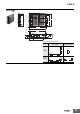
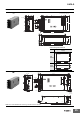
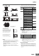
Mounting
S8FS-G015@@@ to 150@@@
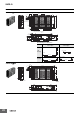
S8FS-G300@@@ and S8FS-G600@@@
Note: Use a metal plate as the mounting surface.
*1. Convection of air.
*2. 2.20 mm min.
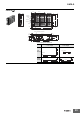
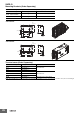
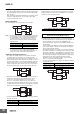
<DIN Rail Mounting>
To mount the Power Supply to a DIN
Rail, hook portion (A) of the Power
Supply onto the DIN Rail and press
the Power Supply in direction (B)
until you hear it lock into place.
To dismount the Block, pull down
portion (C) with a flat-blade
screwdriver and pull out the Block.
Wiring
• Connect the ground completely. A protective earthing terminal
stipulated in safety standards is used. Electric shock or malfunction
may occur if the ground is not connected completely.
• Minor fire may possibly occur. Ensure that input and output
terminals are wired correctly.
• Do not apply more than 150-N force to the terminal block when
tightening it.
• Be sure to remove the sheet covering the Power Supply for
machining before power-ON so that it does not interfere with heat
dissipation.
• Use the following material for the wires to be connected to the
S8FS-G to prevent smoking or ignition caused by abnormal loads.
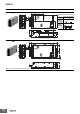
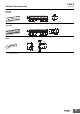
Terminals and Wiring (Screw terminal block type)
Note: The current capacity per output terminal is given in the
following table.
S8FS-G015@@@ to S8FS-G300@@@: 20 A
S8FS-G600@@@: 30 A
Use two terminals together if the current flow is higher than the
rated terminal current.
Terminals and Wiring (Connector type)
Note: 1. The current capacity per output terminal is 5 A.
Use two or more terminals together if the current flow is
higher than the rated terminal current.
2. Do not insert and remove any connector more than 20
times.
3. Refer to Input and Output Connectors on page 14 for the
model numbers of the input and output connectors.
Overcurrent Protection
• Internal parts may possibly deteriorate or be damaged if a short-
circuited, overload, or boost load state continues during operation.
• Internal parts may possibly deteriorate or be damaged if the Power
Supply is used for applications with frequent inrush current or
overloading at the load end. Do not use the Power Supply for such
applications.
20 mm min. 20 mm min.
20 mm min.
20 mm min.
20 mm min. 20 mm min.
20 mm min.
20 mm min.
Ventilation holes
Ventilation
holes
30 mm min.
30 mm min.
30 mm min.
30 mm min.
*1
*2
*1
Rail stopper
(C)
(A)
(B)
Terminals Model
Recommendes
Wire Gauges
Input
S8FS-G015@@@ AWG12-22
S8FS-G030@@@ to 100@@@ AWG12-20
S8FS-G150@@@ to
600
@@@
AWG12-16
Output
S8FS-G01512@ to 01524@
AWG12-22
S8FS-G03024@
S8FS-G01505@
AWG12-20
S8FS-G03012@, 03015@
S8FS-G05015@, 05024@
S8FS-G15048@
S8FS-G05012@
AWG12-18
S8FS-G10024@
S8FS-G03005@
AWG12-16
S8FS-G10015@
S8FS-G15024@
S8FS-G30048@
S8FS-G05005@
AWG12-14S8FS-G10012@
S8FS-G15015@
S8FS-G10005@
AWG12S8FS-G15005@, 15012@
S8FS-G30012@ to 30024@
S8FS-G60015@ to 60048@ AWG10-12
S8FS-G60012@ AWG10
Protective
earth
terminal
S8FS-G015@@@ to 600@@@ AWG12-14
Terminals Model
Recommendes
Wire Gauges
Input S8FS-G01524@E to 15024@EAWG18
Output S8FS-G01524@E to 15024@EAWG18