
Datasheet


S82S
S82S
6
Precautions
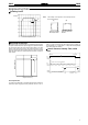
Mounting
To improve and maintain the reliability of the power supply over a
long
period of time, adequate consideration must be given to heat
radiation.
The power supply is designed to radiate heat by means of natural
air-flow. Therefore, mount the power supply so that air flow takes
place
around the power supply
.
Air
When
mounting two or more power supplies side-by-side, allow at
least
10 mm spacing between them, as
shown in the following dia
-
gram.
Forced
air-cooling is recommended.
10
mm min.
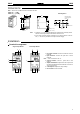
To
mount the power supply on a track, hook portion (A) of the power
supply
to the track and press the power supply to fit in portion (B).
To dismount, pull down portion (C) with a screwdriver and pull out
the
power supply
.
Track stopper
30
mm min.
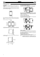
Generating Output Voltage (±)
An output of ± can be generated by using two power supplies as
shown,
because the power supply produces a floating output.
INPUT
INPUT
+V
+V
–V
–V
When connecting the power supplies in series with an operation
amplifier,
connect diodes to the output terminals (as shown by
the
dotted
lines in the figure). Contact your OMRON representative for
details
on connecting diodes.
Serial or Parallel Operation
No
serial or parallel operation is available.
The
positive and negative output terminals of a Dual Output Model
cannot
be connected in series to operate.
+V
INPUT
INPUT
INPUT
INPUT
+V
+V
+V
–V
–V
–V
–V
Input Terminals
Do
not connect the input
line to the other terminals of the power sup
-
ply
or the power supply will be damaged. The input terminals of DC
input models have polarity. If the input polarities are reversed, the
power
supply will be damaged.
Minimum Output Current
The minimum output current of the S82S-7727 and S82S-7728 is
restricted
by the output voltage and control method.
Note: All
the outputs of the S82S-7727 and S82S-7728 are con
-
trolled
by the +V output. If the +V output current falls to 10%
or
less of the rated output, the –V output voltage may drop.