
Datasheet


MY
4
Miniature Power Relays: MY2Z
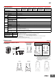
Ordering Information
Note: 1. Ask your OMRON representative for details on the time required to deliver made-to-order products.
2. Ask your OMRON representative for details on product specifications and the ability to manufacture products with voltages other than
the above coil specifications.
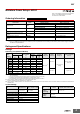
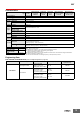
Ratings and Specifications
Ratings
Operating Coil (Standard Models)
Note: 1. The rated current and coil resistance are measured at a coil temperature of 23°C with tolerances of +15%/−20% for the AC rated current and ±15% for the
DC coil resistance.
2. The AC coil resistance and inductance values are reference values only (at 60 Hz).
3. Operating characteristics were measured at a coil temperature of 23°C.
4. The maximum voltage capacity was measured at an ambient temperature of 23°C.
*1. There is variation between products, but actual values are 80% max.
To ensure operation, apply at least 80% of the rated value
*2. There is variation between products, but actual values are 30% minimum for AC and 10% minimum for DC. To ensure release, use a value that is lower than the
specified value.
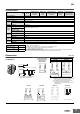
Contact Ratings
*1. With no icing or condensation.
*2. This limitation is due to the diode junction temperature and elements used.
Classification Model
Rated voltage (V)
Standard products Made-to-order items
Standard models MY2Z
100/110 or 200/220 VAC 12, 24, 100/120, or 200/240 VAC
12 or 24 VDC 48 or 100/110 VDC
Models with built-in operation indicators MY2ZN
100/110 or 200/220 VAC 12, 24, 100/120, or 200/240 VAC
24 VDC 12, 48, or 100/110 VDC
Models with built-in diodes MY2Z-D 24 VDC 12 or 100/110 VDC
Models with built-in diodes and operation
indicators
MY2ZN-D2 24 or 100/110 VDC 12 VDC
Models with built-in CR circuits MY2Z-CR 100/110 or 200/220 VAC
Models with built-in CR circuits and operation
indicators
MY2ZN-CR 100/110 VAC 200/220 VAC
Refer to the standards certifications and compliance
section of your OMRON website for the latest
information on certified models.
Whenyourorder,specifytheratedvoltage.
Item Rated current (mA)
Coil resistance
(Ω)
Coil inductance (H)
Must-
operate
voltage (V)
Must-
release
voltage (V)
Maximum
voltage (V)
Power consumption
(VA, W)
Rated
voltage (V)
50 Hz 60 Hz
Armature
OFF
Armature
ON
AC
12 106.5 91 46 0.17 0.33
80% max.
*1
30% min.
*2
110% of rated
voltage
Approx. 0.9 to 1.3
(at 60 Hz)
24 53.8 46 180 0.69 1.3
100/110
11.7/12.9 10/11 3,750 14.54 24.6
110/120
9.9/10.8 8.4/9.2 4,430 19.2 32.1
200/220
6.2/6.8 5.3/5.8 12,950 54.75 94.07
220/240
4.8/5.3 4.2/4.6 18,790 83.5 136.4
DC
12 75 160 0.73 1.37
10% min.
*2
Approx. 0.9
24 36.9 650 3.2 5.72
48 18.5 2,600 10.6 21.0
100/110
9.1/10 11,000 45.6 86.2
Load
Item
Resistive load
Inductive load
(cos φ = 0.4, L/R = 7 ms)
Rated load
5 A at 220 VAC
5 A at 24 VDC
2 A at 220 VAC
2 A at 24 VDC
Rated carry current 5 A
Maximum contact voltage 250 VAC, 125 VDC
Maximum contact current 5 A
Contact configuration DPDT
Contact structure Bifurcated
Contact materials Au plating + Ag
Type
Item
Standard
models
Model with built-in operation
indicator, diode, or CR circuit
Ambient
operating
temperature
*1
−55 to 70° C −55 to 60° C
*2
Ambient
operating
humidity
5% to 85%