
Datasheet


MY
34
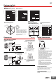
Socket Mounting Plate (t = 1.6) (Unit: mm)
Use a Socket Mounting Plate to mount multiple connection Back-mounting Sockets in a row.
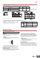
Compliance with Electrical Appliances and Material Safety Act
• All standard models comply with the Electrical Appliances and Material
Safety Act.
• Always protect any exposed terminals (including Socket terminals) after
wiring with insulation tubes or resin coating on PCBs.
* Under the Electrical Appliances and Material Safety Act, do not use any 4-
pole models with a voltage that exceeds 150 VAC. However, this restriction
can be ignored if compliance with the Electrical Appliances and Material
Safety Act is not required.
Safety Precautions
Refer to the Common Relay Precautions.
Handling
For models with a built-in operation indicator, models with a built-in diode, or
high-sensitivity models, check the coil polarity when wiring and wire all
connections correctly (DC operation).
Installation
• There is no specifically required installation orientation, but make sure that
the Relays are installed so that the contacts are not subjected to vibration or
shock in their movement direction.
• Use two M3 screws to attach case-surface-mounted models (MY@F) and
tighten the screws securely (tightening torque: 0.98 N•m).
Using MY-series Relays with Microloads with
Infrequent Operation
If any standard MY-series Relays (e.g., MY4) are used infrequently to switch
microloads, the contacts may become unstable and eventually result in poor
contact. In this case, we recommend using the MY4Z-CBG Series, which has
high contact reliability for microloads (Refer to page 25.)
About the Built-in Diode and CR Elements
The diode or CR element that are built into the Relay are designed to absorb
the reverse voltage from the Relay coil. If a large surge in voltage is applied to
the diode or CR element from an external source, the element will be destroyed.
If there is the possibility of large voltage surges that could be applied to the
elements from an external source, take any necessary surge absorption
measures.
Latching Levers
• Turn OFF the power supply when operating the latching lever. After you use
the latching lever always return it to its original state.
• Do not use the latching lever as a switch.
• The latching lever can be used for 100 operations min.
Relay Replacement
To replace the Relay, turn OFF the power supply to the load and Relay coil
sides to prevent unintended operation and possible electrical shock.
Attaching and Removing Relay Hold-down Clips
When you attach a Hold-down Clip to or remove it from a Socket, wear gloves
or take other measures to prevent injuring your fingers on the Hold-down Clip.
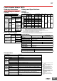
Item
Type
Applicable Sockets
For mounting
1 Socket
For mounting
8 Sockets
For mounting
36 Sockets
Without protective bracket PY08, PY08QN(2), PY11, PY11QN(2), PY14, and PY14QN(2)
PYP-1 PYP-18 PYP-36
Note: You can cut the PYP-18
and PYP-36 to any required
length.
With protective bracket
PY08-Y1, PY08QN(2)-Y1, PY11-Y1, PY11QN(2)-Y1, PY14-Y1,
and PY14QN(2)-Y1
PYP-1 PYP-18 PYP-36
Square
hole
28
42
±0.1
5.1
49
Two, 3.4-dia. holes
The minimum order for the PYP-1 is 10 pieces.
27.4×17 = 465.8
±0.6
492
49
42
±0.1
5.1
21.6
13.1
4.5
3.4
R1.7
27.4
72, oval holes
t = 1.6
±0.15
27.4×17 = 465.8
±0.6
27.4×17 = 465.8
±0.6
492
86.4
39.7
±0.2
39.7
±0.2
5.1
21.6
21.6
13.1
4.5
3.4
R1.7
13.1
27.4
72, oval holes
t = 1.6
±0.15
21.4
+0.2
0
Model
Number of
poles
Coil ratings Contact ratings
MY
1
2
3
6 to 220 VAC
6 to 120 VDC
5 A, 200 VAC
4 *
6 to 110 VAC
6 to 120 VDC
3 A, 115 VAC
Precautions for Correct Use