
Datasheet


MY
32
Engineering Data
Engineering Data
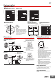
Dimensions (Unit: mm)
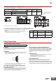
Safety Precautions
PCB Design for Hermetically Sealed Relays
When a Relay with PCB Terminals is mounted, a short-circuit can occur
depending on the design of the PCB pattern because the Relay itself is made
out of metal.
Solution
Refer to the external dimensions of the Relay and design the PCB pattern with
enough space to prevent this problem.
Applicable Sockets
Use only combinations of OMRON Relays and Sockets.
Application Environment for Hermetically Sealed
Relays
Humid environments can cause insulation problems, which may result in short-
circuiting or unintended operation.
Solution
Do not use these Relays in any environment where the Relay will come into
contact with water vapor, condensation, or water droplets. This can reduce the
surface tension of the insulating beads and cause short-circuiting or unintended
operation due to poor insulation.
Relay Replacement
To replace the Relay, turn OFF the power supply to the load and Relay coil
sides to prevent unintended operation and possible electrical shock.
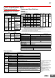
Maximum Switching Capacity Endurance Curve
MY4(Z)H MY4H
Note: The durability of bifurcated contacts is one-half that of single contacts.
DC inductive load
(L/R = 7 ms)
DC contact load
AC contact load
AC inductive load
(cos φ = 0.4)
0.1
0.5
1
5
5 10 50 100 500
Contact voltage (V)
Contact current (A)
110 VAC resistive load
24 VDC resistive load
10
50
100
500
012 3
Contact current (A)
24 VDC inductive load (L/R = 7 ms)
110 VAC inductive load
(cos φ = 0.4)
Number of operations (×10
4
operations)
28.5 max.
2.6
Fourteen, 1.2-dia. × 3 oval holes
35 max. 6.4
22 max.
0.5
Relays with Plug-in Terminals
or Soldered Terminals
MY4(Z)H
Terminal Arrangement/
Internal Connections
(Bottom View)
(The coil has no polarity.)
28.5 max.
1.3 dia.
7
35 max.
5.5
22 max.
1.3 dia.
3.9
Fourteen, 2-dia. holes
6.35
11.85
4.9
4.4
13.2
3.95
6.8
Relays with PCB Terminals
MY4(Z)H-0
PCB Processing Dimensions
(Bottom View)