
Datasheet


31
MY
Hermetically Sealed Relays: MYH
Ordering Information
Relays with Plug-in or Soldered Terminals Relays with PCB Terminals
Ratings and Specifications
Ratings
Operating Coil
Note: 1. The rated current and coil resistance are measured at a coil temperature of 23°C with tolerances of +15%/−20% for the AC rated current and ±15% for the
DC coil resistance.
2. The AC coil resistance and inductance values are reference values only
3. Operating characteristics were measured at a coil temperature of 23°C.
4. The maximum voltage capacity was measured at an ambient temperature of 23°C.
*1. There is variation between products, but actual values are 80% max.
To ensure operation, apply at least 80% of the rated value
*2. There is variation between products, but actual values are 30% minimum for AC and 10% minimum for DC. To ensure release, use a value that is lower than the
specified value.
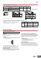
Contact Ratings
* With no icing or condensation.
Characteristics
Note:
The above values are initial values.
*1.
Measurement conditions: 1 A at 5 VDC using the voltage drop method
*2.
Measurement conditions: With rated operating power applied, not including contact
bounce.
Ambient temperature condition: 23° C
*3.
Measurement conditions: For 500 VDC applied to the same location as for dielectric
strength measurement.
*4.
This value is for bifurcated contacts.
*5.
Ambient temperature condition: 23° C
*6.
This value was measured at a switching frequency of 120 operations per minute.
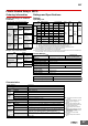
Whenyourorder,specifytheratedvoltage.
Type 4 poles
Classification Model Rated voltage (V)
Models with single
contacts
MY4H
24, 100/110, or 110/120 VAC
12, 24, 48, or 100/110 VDC
Bifurcated contacts MY4ZH
24, 100/110, or 110/120 VAC
12, 24, 48, or 100/110 VDC
Type 4 poles
Classification Model Rated voltage (V)
Models with single
contacts
MY4H-0
110/120 VAC
24 VDC
Bifurcated
contacts
MY4ZH-0 24 or 100/110 VDC
Item Rated current (mA)
Coil
resistance (Ω)
Coil inductance (H)
Must-operate
voltage (V)
Must-release
voltage (V)
Maximum
voltage (V)
Power consumption
(VA, W)
Rated voltage (V) 50 Hz 60 Hz Armature OFF Armature ON
AC
24 53.8 46 180 0.69 1.3
80% max.
*1
30% min.
*2
110% of
rated voltage
Approx. 0.9 to 1.3
(at 60 Hz)
100/110
11.7/12.9 10/11 3,750 14.54 24.6
110/120
9.9/10.8 8.4/9.2 4,430 19.2 32.1
DC
12 75 160 0.73 1.37
10% min.
*2
Approx. 0.9
24 36.9 650 3.2 5.72
48 18.5 2,600 10.6 21.0
100/110
9.1/10 11,000 45.6 86.2
Load
Models with single
contacts
Bifurcated contacts
Item
Resistive
load
Inductive load
cos
φ
= 0.4
L/R = 7 ms
Resistive
load
Inductive load
cos
φ
= 0.4
L/R = 7 ms
Rated load
3 A at 110 VAC
3 A at 24 VDC
0.8 A at 110 VAC
1.5 A at 24 VDC
3 A at 110 VAC
3 A at 24 VDC
0.8 A at 110 VAC
1.5 A at 24 VDC
Rated carry
current
3 A 3 A
Maximum contact
voltage
125 VAC
125 VDC
125 VAC
125 VDC
Maximum contact
current
3 A 3 A
Contact structure Single Bifurcated
Contact materials Au plating + Ag
Ambient operating
temperature
−25 to 60° C
*
Ambient operating
humidity
5% to 85%
Contact resistance
*
1
50 m
Ω
max.
Operation time
*
2
20 ms max.
Release time
*
2
20 ms max.
Maximum
operating
frequency
Mechanical
18,000 operations/h
Rated load
1,800 operations/h
Insulation resistance
*
4
100 M
Ω
min.
Dielectric
strength
Between coil
and contacts
1,000 VAC at 50/60 Hz for 1 min.
(700 VAC between contacts of the same polarity.)
Between contacts
of different polarity
Vibration
resistance
Destruction
10 to 55 to 10 Hz, 0.5-mm single amplitude
(1.0-mm double amplitude)
Malfunction
10 to 55 to 10 Hz, 0.5-mm single amplitude
(1.0-mm double amplitude)
Shock
resistance
Destruction
1,000 m/s
2
Malfunction
200 m/s
2
Endurance
Mechanical
50,000,000 operations (5,000,000 operations
*
4
) min.
(operating frequency: 18,000 operations/h)
Electrical
*
5
100,000 operations (50,000 operations
*
4
) min. rated
load, switching frequency: 1,800 operations/h)
Failure rate P value
(reference value)
*
6
Single contacts: 100
µ
A at 1 VDC
Bifurcated contacts: 100
µ
A at 100 mVDC
Weight
Approx. 50 g