
Datasheet


MY
30
Engineering Data
Engineering Data
MY2K(-02)
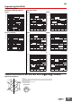
Maximum Switching Capacity Endurance Curve
MY2K 100 VAC MY2K 24 VDC
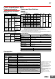
Malfunctioning Shock Magnetic Interference
(External Magnetic Field)
Latching Deterioration Over
Time
DC inductive load
(L/R = 7 ms)
DC resistive load
AC resistive load
AC inductive load
(cos φ = 0.4)
10
0.1
0.5
1
5
5 10 50 100 500
Contact voltage (V)
Contact current (A)
30 VDC resistive load
110 VAC resistive load
220 VAC resistive load
10
50
100
500
012 3
Contact current (A)
Number of operations (×10
4
operations)
30 VDC inductive load
(L/R = 7 ms)
110 VAC inductive load
(cos φ = 0.4)
220 VAC
inductive load
(cos φ = 0.4)
10
1
50
100
500
0 0.5 1.5
Contact current (A)
Number of operations (×10
4
operations)
Energized
Not energized
Y
X
Z’
X’
Z
Y’
900
1000
1000
400
400
800
700
400
400
1000
350
900
1000
300
1000
Unit: m/s
2
Armature deviation
when set
N = 20
Measurement: Shock was applied 2
times each in 6 directions along 3
axes with the Relay energized and not
energized to check the shock values
that cause the Relay to malfunction.
Criteria: Non-energized: 200 m/s
2
Energized: 200 m/s
2
Reset voltage
Set voltage
Uniform magnetic field strength (0e)
(Average values)
SNSN
Percentage
change (%)
80
80
60
60
40
20
−20
−40
−60
40
8060
−80
N = 5
Measurement: The percentage of change in the operating and
release voltages in a uniform external magnetic field
were measured (worst magnetic field direction).
40
Average value
60
90
80
70
100
0 50 100
300 500 1,000 5,000 10,000
Elapsed time (h)
Latching deterioration over time (%)
N = 24
Measurement: The rate of deterioration in latching ability was
measured over time with the Relay left at a normal temperature
(20 to 30°C) after latching by applying the rated voltage.
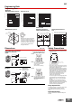
Dimensions (Unit: mm)
28 max.
6.3
2.6
0.5
21.5 max.
0.5
36 max. 6.4
Ten, 1.2-dia. × 2.2 oval holes
Relays with Plug-in Terminals
or Soldered Terminals
MY2K
Terminal Arrangement/Internal
Connections (Bottom View)
For AC
Note: R is a resistor for ampere-
turn correction. This resistor
is built-in to 50-VAC and
higher models.
(The coil has no polarity.)
Note: Pay close attention to the set
coil and reset coil polarities. If
the connections are not
correct, unintended operation
may occur.
For DC
28 max.
6.3
2.6
1
0.5
21.5 max.
36 max. 4
3.5
Ten, 1.3-dia. holes
Relays with PCB Terminals
MY2K-02
PCB Processing Dimensions
(Bottom View)
Note: The dimensional
tolerance is ±0.1.
Safety Precautions
• For applications that use a 200 VAC power
supply, connect external resistors Rs and Rr to
a 100 VAC Relay.
• Do not apply a voltage to the set and reset coils at the
same time. If you apply the rated voltage to both coils
simultaneously, the Relay will be set.
• The minimum pulse width in the performance column is
the value for the following measurement conditions: an
ambient temperature of 23° C with the rated operating
voltage applied to the coil. The performance values
given here may not be satisfied due to use over time
and a reduction in latching performance due to
changes in the ambient temperature or in the
conditions of the application circuit.
For actual use, apply the rated operating voltage with a
pulse width based on the actual load and reset the
Relay at least once per year to prevent degradation
over time.
• If the Relay is used in an environment with strong
magnetic fields, the surrounding magnetic field can
demagnetize the magnetic body and cause unintended
operation. Therefore, do not use these Relays in
environments with strong magnetic fields.
Relay Replacement
To replace the Relay, turn OFF the power supply
to the load and Relay coil sides to prevent
unintended operation and possible electrical
shock.
Applicable Sockets
Use only combinations of OMRON Relays and
Sockets.
14
Rr
Rs
Rs: 7.3 kΩ, 3 W min.
Rr: 14.3 kΩ, 1 W min.
Reset power supply
Set power supply
13
9101112
58
14